
Concept explainers
Videos
(a)
Find whether the slipping occurs between the belt and either cylinder.
(a)
Explanation of Solution
The force pulled between cylinders A and B (P) is
The weight of the cylinder A
The weight of the cylinder B
The coefficient of the static friction
The coefficient of the kinetic friction
The radius of the cylinder A
The radius of the cylinder B
Calculation:
Consider the acceleration due to gravity (g) as
Convert the unit of the radius of the cylinder A
Convert the unit of the radius of the cylinder B
Consider that no slipping occurs.
Calculate the acceleration of the belt
Calculate the mass of the cylinder A
Substitute
Calculate the mass of the cylinder B
Substitute
Calculate the mass moment of inertia of the cylinder A
Substitute
Calculate the mass moment of inertia of the cylinder B
Substitute
Show the free body diagram of the cylinder A as in Figure 1.
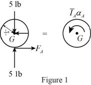
Here,
Refer to Figure 1.
Calculate the moment about point G by applying the equation of equilibrium:
Substitute
Show the free body diagram of the cylinder B as in Figure 2.
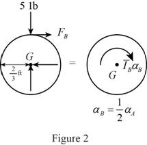
Here,
Refer to Figure 2.
Calculate the moment about point G by applying the equation of equilibrium:
Substitute
Show the free body diagram of the belt as in Figure 3.
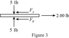
Refer to Figure 3.
Calculate the horizontal forces by applying the equation of equilibrium:
Sum of horizontal forces is equal to 0.
Calculate the angular acceleration of the cylinder A
Substitute
Calculate the horizontal force of the cylinder A
Substitute
Calculate the horizontal force of the cylinder B
Substitute
Calculate the magnitude of the friction force
Substitute
The horizontal forces of the cylinder A and B are greater than the magnitude of the friction force
Therefore, there is no slipping occurs between cylinders and belt.
(b)
Find the angular acceleration of each cylinder
(b)
Answer to Problem 16.40P
The angular acceleration of each cylinder
Explanation of Solution
The force pulled between cylinders A and B (P) is
The weight of the cylinder A
The weight of the cylinder B
The coefficient of the static friction
The coefficient of the kinetic friction
The radius of the cylinder A
The radius of the cylinder B
Calculation:
Refer the part (a).
Consider the no slipping occur at cylinder B.
Therefore, the angular acceleration of the cylinder B is
Calculate the angular acceleration of the cylinder A
Substitute
Calculate the angular acceleration of the cylinder B
Substitute
Hence, the angular acceleration of each cylinder
Want to see more full solutions like this?
Chapter 16 Solutions
Vector Mechanics for Engineers: Statics and Dynamics


- Please do not use any AI tools to solve this question. I need a fully manual, step-by-step solution with clear explanations, as if it were done by a human tutor. No AI-generated responses, please.arrow_forwardPlease do not use any AI tools to solve this question. I need a fully manual, step-by-step solution with clear explanations, as if it were done by a human tutor. No AI-generated responses, please.arrow_forwardCE-112 please solve this problem step by step and give me the correct answerarrow_forward
- CE-112 please solve this problem step by step and give me the correct asnwerarrow_forwardthis is an old practice exam, the answer is Ax = -4, Ay = -12,Az = 32.5, Bx= 34, Bz = 5, By = 0 but how?arrow_forwardThis is an old practice exam, the answer is Ax = Az = 0, Ay = 2000, TDE = 4750, Cx = 2000, Cy = 2000, Cz = -800 but how?arrow_forward
- this is an old practice exam, the answer is Fmin = 290.5lb but howarrow_forwardThis is an exam review question. The answer is Pmin = 622.9 lb but whyarrow_forwardPlease do not use any AI tools to solve this question. I need a fully manual, step-by-step solution with clear explanations, as if it were done by a human tutor. No AI-generated responses, please.arrow_forward
- Please do not use any AI tools to solve this question. I need a fully manual, step-by-step solution with clear explanations, as if it were done by a human tutor. No AI-generated responses, please.arrow_forwardPlease do not use any AI tools to solve this question. I need a fully manual, step-by-step solution with clear explanations, as if it were done by a human tutor. No AI-generated responses, please.arrow_forwardThis is an old practice exam. Fce = 110lb and FBCD = 62 lb but whyarrow_forward
 International Edition---engineering Mechanics: St...Mechanical EngineeringISBN:9781305501607Author:Andrew Pytel And Jaan KiusalaasPublisher:CENGAGE L