
Vector Mechanics for Engineers: Statics and Dynamics
12th Edition
ISBN: 9781259638091
Author: Ferdinand P. Beer, E. Russell Johnston Jr., David Mazurek, Phillip J. Cornwell, Brian Self
Publisher: McGraw-Hill Education
expand_more
expand_more
format_list_bulleted
Concept explainers
Videos
Textbook Question
Chapter 16.2, Problem 16.122P
End A of the 6-kg uniform rod AB rests on the inclined surface, while end B is attached to a collar of negligible mass that can slide along the vertical rod shown. When the rod is at rest, a vertical force P is applied at B, causing end B of the rod to start moving upward with an acceleration of 4 m/s2. Knowing that θ = 35°, determine the force P.
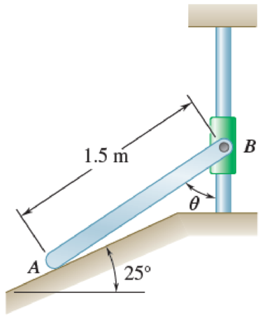
Fig. P16.121 and P16.122
Expert Solution & Answer
Want to see the full answer?
Check out a sample textbook solution
Students have asked these similar questions
=
The steel curved bar shown has rectangular cross-section with a radial height h = 6 mm and thickness b = 4mm. The
radius of the centroidal axis is R = 80 mm. A force P = 10 N is applied as shown. Assume the steel modulus of
207,000 MPa and G = 79.3(103) MPa, repectively.
elasticity and shear modulus E =
Find the vertical deflection at point B. Use Castigliano's method for a curved flexural member and since R/h > 10,
neglect the effect of shear and axial load, thereby assuming that deflection is due to merely the bending moment.
Note the inner and outer radii of the curves bar are:
r = 80 + ½ (6) = 83 mm, r₁ = 80 − ½ (6) = 77 mm
2
2
Sπ/2 sin² 0 d = √π/² cos² 0 d0 =
Π
0
4
大
C
R
B
P
The steel eyebolt shown in the figure is loaded with a force F = 75 lb. The eyebolt is formed from round wire of
diameter d = 0.25 in to a radius R₁ = 0.50 in in the eye and at the shank.
Estimate the stresses at the inner and outer surfaces at section A-A.
Notice at the section A-A:
r₁ = 0.5 in, ro
= 0.75 in
rc
=
0.5 + 0.125 = 0.625 in
Ri
200
F
FA
I have the fallowing question and solution from a reeds naval arc book. Im just confused as to where this answer came from and the formulas used. Wondering if i could have this answer/ solution broken down and explained in detail.
A ship of 7000 tonne displacement has a waterplane areaof 1500 m2. In passing from sea water into river water of1005 kg/m3 there is an increase in draught of 10 cm. Find the Idensity of the sea water.
picture of the "answer" is attached
Chapter 16 Solutions
Vector Mechanics for Engineers: Statics and Dynamics
Ch. 16.1 - Two pendulums, A and B, with the masses and...Ch. 16.1 - Two pendulums, A and B, with the masses and...Ch. 16.1 - Two solid cylinders, A and B, have the same mass m...Ch. 16.1 - Prob. 16.1FBPCh. 16.1 - Prob. 16.2FBPCh. 16.1 - Prob. 16.3FBPCh. 16.1 - The 400-lb crate shown is lowered by means of two...Ch. 16.1 - A 60-lb uniform thin panel is placed in a truck...Ch. 16.1 - A 60-lb uniform thin panel is placed in a truck...Ch. 16.1 - A loading car is at rest on a track forming an...
Ch. 16.1 - A 2100-lb rear-wheel-drive tractor carries a 900...Ch. 16.1 - A uniform rod BC of mass 4 kg is connected to a...Ch. 16.1 - A 2000-kg truck is being used to lift a 400-kg...Ch. 16.1 - The support bracket shown is used to transport a...Ch. 16.1 - Prob. 16.8PCh. 16.1 - A 20-kg cabinet is mounted on casters that allow...Ch. 16.1 - Solve Prob. 16.9, assuming that the casters are...Ch. 16.1 - Prob. 16.11PCh. 16.1 - Prob. 16.12PCh. 16.1 - The retractable shelf shown is supported by two...Ch. 16.1 - Bars AB and BE, each with a mass of 4 kg, are...Ch. 16.1 - At the instant shown, the tensions in the vertical...Ch. 16.1 - Three bars, each of mass 3 kg, are welded together...Ch. 16.1 - Members ACE and DCB are each 600 mm long and are...Ch. 16.1 - A prototype rotating bicycle rack is designed to...Ch. 16.1 - The control rod AC is guided by two pins that...Ch. 16.1 - The coefficients of friction between the 30-lb...Ch. 16.1 - Prob. 16.21PCh. 16.1 - Prob. 16.22PCh. 16.1 - For a rigid body in translation, show that the...Ch. 16.1 - For a rigid body in centroidal rotation, show that...Ch. 16.1 - It takes 10 min for a 2.4-Mg flywheel to coast to...Ch. 16.1 - The rotor of an electric motor has an angular...Ch. 16.1 - The 10-in.-radius brake drum is attached to a...Ch. 16.1 - The 10-in.-radius brake drum is attached to a...Ch. 16.1 - The 100-mm-radius brake drum is attached to a...Ch. 16.1 - The 180-mm-radius disk is at rest when it is...Ch. 16.1 - Solve Prob. 16.30, assuming that the direction of...Ch. 16.1 - In order to determine the mass moment of inertia...Ch. 16.1 - The flywheel shown has a radius of 20 in., a...Ch. 16.1 - Each of the double pulleys shown has a mass moment...Ch. 16.1 - Two disks A and B, of mass mA = 2 kg and mB = 4...Ch. 16.1 - Two disks A and B, of mass mA = 2 kg and mB = 4...Ch. 16.1 - Gear A weighs 1 lb and has a radius of gyration of...Ch. 16.1 - The 25-lb double pulley shown is at rest and in...Ch. 16.1 - A belt of negligible mass passes between cylinders...Ch. 16.1 - Prob. 16.40PCh. 16.1 - Disk A has a mass of 6 kg and an initial angular...Ch. 16.1 - Prob. 16.42PCh. 16.1 - Disk A has a mass mA = 4 kg, a radius rA = 300 mm,...Ch. 16.1 - Disk B is at rest when it is brought into contact...Ch. 16.1 - Prob. 16.45PCh. 16.1 - Prob. 16.46PCh. 16.1 - For a rigid body in plane motion, show that the...Ch. 16.1 - A uniform slender rod AB rests on a frictionless...Ch. 16.1 - Prob. 16.49PCh. 16.1 - Prob. 16.50PCh. 16.1 - Prob. 16.51PCh. 16.1 - A 250-lb satellite has a radius of gyration of 24...Ch. 16.1 - A rectangular plate of mass 5 kg is suspended from...Ch. 16.1 - Prob. 16.54PCh. 16.1 - A drum with a 200-mm radius is attached to a disk...Ch. 16.1 - A drum with a 200-mm radius is attached to a disk...Ch. 16.1 - The 12-lb uniform disk shown has a radius of r =...Ch. 16.1 - Prob. 16.58PCh. 16.1 - Prob. 16.59PCh. 16.1 - 16.60 and 16.61The 400-lb crate shown is lowered...Ch. 16.1 - Prob. 16.61PCh. 16.1 - Two uniform cylinders, each of weight W = 14 lb...Ch. 16.1 - Prob. 16.63PCh. 16.1 - Prob. 16.64PCh. 16.1 - A uniform slender bar AB with a mass m is...Ch. 16.1 - Prob. 16.66PCh. 16.1 - 16.66 through 16.68A thin plate of the shape...Ch. 16.1 - 16.66 through 16.68A thin plate of the shape...Ch. 16.1 - A sphere of radius r and mass m is projected along...Ch. 16.1 - Solve Prob. 16.69, assuming that the sphere is...Ch. 16.1 - A bowler projects an 8-in.-diameter ball weighing...Ch. 16.1 - Prob. 16.72PCh. 16.1 - A uniform sphere of radius r and mass m is placed...Ch. 16.1 - A sphere of radius r and mass m has a linear...Ch. 16.2 - A cord is attached to a spool when a force P is...Ch. 16.2 - Prob. 16.5CQCh. 16.2 - Prob. 16.6CQCh. 16.2 - Prob. 16.7CQCh. 16.2 - Prob. 16.5FBPCh. 16.2 - Two identical 4-lb slender rods AB and BC are...Ch. 16.2 - Prob. 16.7FBPCh. 16.2 - Prob. 16.8FBPCh. 16.2 - Show that the couple I of Fig. 16.15 can be...Ch. 16.2 - A uniform slender rod of length L = 900 mm and...Ch. 16.2 - A crate of mass 80 kg is held in the position...Ch. 16.2 - A uniform slender rod of length L = 36 in. and...Ch. 16.2 - In Prob. 16.78, determine (a) the distance h for...Ch. 16.2 - An athlete performs a leg extension on a machine...Ch. 16.2 - Prob. 16.81PCh. 16.2 - A turbine disk weighing 50 lb rotates at a...Ch. 16.2 - The 80-lb tailgate of a car is supported by the...Ch. 16.2 - A uniform rod of length L and mass m is supported...Ch. 16.2 - Three stage lights are mounted on a pipe fixture...Ch. 16.2 - An adapted launcher uses a torsional spring about...Ch. 16.2 - A 4-kg slender rod is welded to the edge of a 3-kg...Ch. 16.2 - Prob. 16.88PCh. 16.2 - The object ABC consists of two slender rods welded...Ch. 16.2 - A 3.5-kg slender rod AB and a 2-kg slender rod BC...Ch. 16.2 - A 9-kg uniform disk is attached to the 5-kg...Ch. 16.2 - Derive the equation MC=IC for the rolling disk of...Ch. 16.2 - Prob. 16.93PCh. 16.2 - Prob. 16.94PCh. 16.2 - Prob. 16.95PCh. 16.2 - Prob. 16.96PCh. 16.2 - A 40-kg flywheel of radius R = 0.5 m is rigidly...Ch. 16.2 - Prob. 16.98PCh. 16.2 - 16.98 through 16.101A drum of 80-mm radius is...Ch. 16.2 - 16.98 through 16.101A drum of 80-mm radius is...Ch. 16.2 - 16.98 through 16.101A drum of 80-mm radius is...Ch. 16.2 - 16.102 through 16.105A drum of 4-in. radius is...Ch. 16.2 - 16.102 through 16.105A drum of 4-in. radius is...Ch. 16.2 - 16.102 through 16.105A drum of 4-in. radius is...Ch. 16.2 - 16.102 through 16.105A drum of 4-in. radius is...Ch. 16.2 - 16.106 and 16.107A 12-in.-radius cylinder of...Ch. 16.2 - 16.106 and 16.107A 12-in.-radius cylinder of...Ch. 16.2 - Gear C has a mass of 5 kg and a centroidal radius...Ch. 16.2 - Two uniform disks A and B, each with a mass of 2...Ch. 16.2 - A single-axis personal transport device starts...Ch. 16.2 - A hemisphere of weight W and radius r is released...Ch. 16.2 - A hemisphere of weight W and radius r is released...Ch. 16.2 - The center of gravity G of a 1.5-kg unbalanced...Ch. 16.2 - A small clamp of mass mB is attached at B to a...Ch. 16.2 - Prob. 16.115PCh. 16.2 - A 4-lb bar is attached to a 10-lb uniform cylinder...Ch. 16.2 - The uniform rod AB with a mass m and a length of...Ch. 16.2 - Prob. 16.118PCh. 16.2 - Prob. 16.119PCh. 16.2 - Prob. 16.120PCh. 16.2 - End A of the 6-kg uniform rod AB rests on the...Ch. 16.2 - End A of the 6-kg uniform rod AB rests on the...Ch. 16.2 - End A of the 8-kg uniform rod AB is attached to a...Ch. 16.2 - The 4-kg uniform rod ABD is attached to the crank...Ch. 16.2 - The 3-lb uniform rod BD is connected to crank AB...Ch. 16.2 - The 3-lb uniform rod BD is connected to crank AB...Ch. 16.2 - The test rig shown was developed to perform...Ch. 16.2 - Solve Prob. 16.127 for = 90. 16.127The test rig...Ch. 16.2 - The 4-kg uniform slender bar BD is attached to bar...Ch. 16.2 - The motion of the uniform slender rod of length L...Ch. 16.2 - At the instant shown, the 20-ft-long, uniform...Ch. 16.2 - A driver starts his car with the door on the...Ch. 16.2 - Prob. 16.133PCh. 16.2 - The hatchback of a car is positioned as shown to...Ch. 16.2 - The 6-kg rod BC connects a 10-kg disk centered at...Ch. 16.2 - Prob. 16.136PCh. 16.2 - In the engine system shown, l = 250 mm and b = 100...Ch. 16.2 - Solve Prob. 16.137 when = 90. 16.137In the engine...Ch. 16.2 - The 4-lb uniform slender rod AB, the 8-lb uniform...Ch. 16.2 - The 4-lb uniform slender rod AB, the 8-lb uniform...Ch. 16.2 - Two rotating rods in the vertical plane are...Ch. 16.2 - Two rotating rods in the vertical plane are...Ch. 16.2 - Two disks, each with a mass m and a radius r, are...Ch. 16.2 - A uniform slender bar AB of mass m is suspended as...Ch. 16.2 - A uniform rod AB, of mass 15 kg and length 1 m, is...Ch. 16.2 - The uniform slender 2-kg bar BD is attached to the...Ch. 16.2 - Prob. 16.147PCh. 16.2 - Prob. 16.148PCh. 16.2 - Prob. 16.149PCh. 16.2 - Prob. 16.150PCh. 16.2 - (a) Determine the magnitude and the location of...Ch. 16.2 - Prob. 16.152PCh. 16 - A cyclist is riding a bicycle at a speed of 20 mph...Ch. 16 - The forklift truck shown weighs 3200 lb and is...Ch. 16 - The total mass of the Baja car and driver,...Ch. 16 - Identical cylinders of mass m and radius r are...Ch. 16 - Prob. 16.157RPCh. 16 - The uniform rod AB of weight W is released from...Ch. 16 - Prob. 16.159RPCh. 16 - Prob. 16.160RPCh. 16 - A cylinder with a circular hole is rolling without...Ch. 16 - Two 3-kg uniform bars are connected to form the...Ch. 16 - A crate of mass 80 kg is held in the position...Ch. 16 - The Geneva mechanism shown is used to provide an...
Additional Engineering Textbook Solutions
Find more solutions based on key concepts
How is the hydrodynamic entry length defined for flow in a pipe? Is the entry length longer in laminar or turbu...
Fluid Mechanics: Fundamentals and Applications
The solid steel shaft AC has a diameter of 25 mm and is supported by smooth bearings at D and E. It is coupled ...
Mechanics of Materials (10th Edition)
In Exercises 1 through 22, determine the output displayed in the text box or list box by the lines of code.
Introduction To Programming Using Visual Basic (11th Edition)
A nozzle at A discharges water with an initial velocity of 36 ft/s at an angle with the horizontal. Determine ...
Vector Mechanics For Engineers
What types of coolant are used in vehicles?
Automotive Technology: Principles, Diagnosis, And Service (6th Edition) (halderman Automotive Series)
Knowledge Booster


Learn more about
Need a deep-dive on the concept behind this application? Look no further. Learn more about this topic, mechanical-engineering and related others by exploring similar questions and additional content below.Similar questions
- Problem A2 long steel tube has a rectangular cross-section with outer dimensions of 20 x 20 mm and a uniform wall thickness of 2. The tube is twisted along its length with torque, T. The tube material is 1045 CD steel with shear yield strength of S,, =315 MPa. Assume shear modulus, G = 79.3GPa. (a) Estimate the maximum torque that can be applied without yielding (b) Estimate the torque required to produce 5 degrees total angle of twist over the length of the tube. (c) What is the maximum torque that can be applied without yielding, if a solid rectangular shaft with dimensions of 20 x 20 is used? You may use the exact solution.arrow_forwardA simply supported beam is loaded as shown. Considering symmetry, the reactions at supports A and B are R₁ = R₂ = wa 2 Using the singularity method, determine the shear force V along the length of the beam as a function of distance x from the support A. A B Ir. 2a За W C R₁₂ x 2. Using the singularity method, determine the bending M along the length of the beam as a function of distance x, from the support A. 3. Using the singularity method, determine the beam slope and deflection along the length of the beam as a function of the distance x, from the support A. Assume the material modulus of elasticity, E and the moment of inertia of the beam cross-section, I are given.arrow_forwardA steel tube, 2 m long, has a rectangular cross-section with outer dimensions of 20 × 30 mm and a uniform wall thickness of 1 mm. The tube is twisted along its length with torque, T. The tube material is 1018 CD steel with shear yield strength of Ssy =185 MPa. Assume shear modulus, G = 79.3GPa. (a) Estimate the maximum torque that can be applied without yielding.- (b) Estimate the torque required to produce 3 degrees total angle of twist over the length of the tube. (c) What is the maximum torque that can be applied without yielding, if a solid rectangular shaft with dimensions of 20 x 30 mm is used? You may use the exact solution:arrow_forward
- |The typical cruising altitude of a commercial jet airliner is 10,700 m above sea level where the local atmospheric temperature is 219 K, and the pressure is 0.25 bar. The aircraft utilizes a cold air-standard Brayton cycle as shown with a volume flow rate of 1450 m³/s. The compressor pressure ratio is 50, and the maximum cycle temperature is 1700 K. The compressor and turbine isentropic efficiencies are 90%. Neglect kinetic and potential energy effects in this problem. Assume constant specific heats with k=1.4, Ra=0.287 kJ/kg- K, Cp=1.0045 kJ/kg-K, and cv = 0.7175 kJ/kg-K. a) Draw a T-s diagram for this cycle on the diagram provided. b) Fill in the table below with the missing information. T[K] Heat exchanger Heat exchanger State P [bar] 1 0.25 2s 2 3 4s 4 Turbine c) (5pts) Determine the inlet air density in [kg/m³] (at state 1), and the system mass flowrate in [kg/s]. d) (10pts) Determine the net power developed in [MW]. Be sure to draw each component you are analyzing, define the…arrow_forwardOn the axis provide, draw a corresponding T-s diagram for the Brayton cycle shown given the following information: iv. V. vi. Compressor 1 is reversible, but Compressor 2 and the turbine are irreversible. The pressure drops through the regenerator are combustors are negligible. The pressures at state (1) and state (10) are equal to the atmospheric pressure. T 8 Regenerator fmm mmm Qin Combustor Compressor Compressor Turbine W cycle Intercooler mm Courarrow_forwardFor parts a) through e), consider the two power cycles shown in the diagram at the right, Cycle A: 1-2-3-4-1, and Cycle B: 1-2-3-4-1. a) What type of power cycles are shown? b) Which of cycles has a higher efficiency? c) Which of the cycles has a higher work output? d) For either cycle, would increasing the maximum cycle temperature (3) increase or decrease the efficiency? Cycle A: 1-2-3-4-1 3 3 Cycle B: 1-2-3-4-1 1 e) For either cycle, would decreasing the minimum cycle temperature (1) increase or decrease the efficiency? f) On the axis provide, draw a corresponding T-s diagram for the Rankine cycle shown given the following information: i. All turbines and pumps in the system are irreversible. ii. 111. The turbine inlet conditions (states 1 and 2) are superheated, while the 2nd stage turbine outlet is a saturated mixture. The condenser outlet state (4) and the CFWH outlet state (7) are saturated liquid. 2 Steam generator Condenser www Closed feedwater heater (1-y) T Pump Trap 8 (y) Sarrow_forward
- Problem 4 A glass sphere with a 30 mm diameter is pressed against a flat carbon steel plate with a force of 5 N. Assume. For glass: E = 46.2 GPa, -0.245 and for steel E, 207 GPa, (a) Determine the radius of the contact surface. -0.292 (4 (b) Determine the maximum pressure at the contact surface. (4 (c) Calculate the principal stresses d., and a, in the glass sphere at the depth=0.037 mm. (d) Maximum shear stress in the glass sphere at the depth: 0.037 mm. (t (4 (e) Draw the Mohr circles for the stresses and show the point corresponding to the maximum shear stress. (3arrow_forwardSteam is the working fluid in the vapor power cycle with reheat shown in the figure. The mass flow rate is 0.5 kg/s, and the turbines and pump operate isentropically. The temperature at the inlet of both turbine stages (i.e. states 1 and 3) is 400 °C The condenser outlet is saturated liquid. 1. Fill in the table below with the missing information. Reheat section High- pressure turbine State P [bar] h [kJ/kg] s [kJ/kg-K] x [-] Steam generator 1 140 Condenser Pump 2 40 5 3 4 4 5 6 2.Draw a T-s diagram for this cycle on the diagram provided 3. Determine the net power output of this cycle in [kW]. Be sure to draw the component(s) you are analyzing, define the system, and apply conservation of energy in the space below. 4.Determine the total heat transferred into the system in [kW]. Be sure to draw the component you are analyzing, define the system, and apply conservation of energy in the space bel 5.Determine the cycle efficiency. Low-pressure turbinearrow_forwardCalculate the moment of F about axis AB. Express the moment as a Cartesian vector, and then state its magnitude. The radii of the curved sections are all 0.5 m. F acts on the bottom center of the hook, and the hook lies in the yz plane.arrow_forward
- Determine the moment created by the force FAB about the point E. Assume FAB = 800 lbs. Express your answer as a Cartesian vector (ME) and state the magnitude of the moment.arrow_forwardDetermine the couple moment acting on the beam. Express it as a Cartesian vector.arrow_forwardDetermine Cartesian vector expressions for reaction forces at A and B i.e. determine FA and FB.arrow_forward
arrow_back_ios
SEE MORE QUESTIONS
arrow_forward_ios
Recommended textbooks for you
 Elements Of ElectromagneticsMechanical EngineeringISBN:9780190698614Author:Sadiku, Matthew N. O.Publisher:Oxford University Press
 Mechanics of Materials (10th Edition)Mechanical EngineeringISBN:9780134319650Author:Russell C. HibbelerPublisher:PEARSON
 Thermodynamics: An Engineering ApproachMechanical EngineeringISBN:9781259822674Author:Yunus A. Cengel Dr., Michael A. BolesPublisher:McGraw-Hill Education
 Control Systems EngineeringMechanical EngineeringISBN:9781118170519Author:Norman S. NisePublisher:WILEY
 Mechanics of Materials (MindTap Course List)Mechanical EngineeringISBN:9781337093347Author:Barry J. Goodno, James M. GerePublisher:Cengage Learning
 Engineering Mechanics: StaticsMechanical EngineeringISBN:9781118807330Author:James L. Meriam, L. G. Kraige, J. N. BoltonPublisher:WILEY
Elements Of Electromagnetics
Mechanical Engineering
ISBN:9780190698614
Author:Sadiku, Matthew N. O.
Publisher:Oxford University Press
Mechanics of Materials (10th Edition)
Mechanical Engineering
ISBN:9780134319650
Author:Russell C. Hibbeler
Publisher:PEARSON
Thermodynamics: An Engineering Approach
Mechanical Engineering
ISBN:9781259822674
Author:Yunus A. Cengel Dr., Michael A. Boles
Publisher:McGraw-Hill Education
Control Systems Engineering
Mechanical Engineering
ISBN:9781118170519
Author:Norman S. Nise
Publisher:WILEY
Mechanics of Materials (MindTap Course List)
Mechanical Engineering
ISBN:9781337093347
Author:Barry J. Goodno, James M. Gere
Publisher:Cengage Learning
Engineering Mechanics: Statics
Mechanical Engineering
ISBN:9781118807330
Author:James L. Meriam, L. G. Kraige, J. N. Bolton
Publisher:WILEY
Understanding Thermal Radiation; Author: The Efficient Engineer;https://www.youtube.com/watch?v=FDmYCI_xYlA;License: Standard youtube license