
Concept explainers
Videos
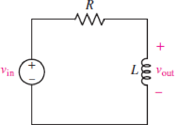
For the RL circuit in Fig. 15.52, (a) determine the transer function defined as H(jω) = vout/vin; (b) for the case of R = 200 Ω and L = 5 mH, construct a plot of the magnitude and phase as a function of frequency; and (c) evaluate the magnitude and phase at a frequency of 10 kHz.
FIGURE 15.52
(a)
Find the transfer function
Answer to Problem 1E
The transfer function
Explanation of Solution
Given data:
Refer to Figure 15.52 in the textbook.
Formula used:
Write the expression to calculate the impedance of the passive elements resistor and inductor.
Here,
Calculation:
The given RL circuit is drawn as Figure 1.
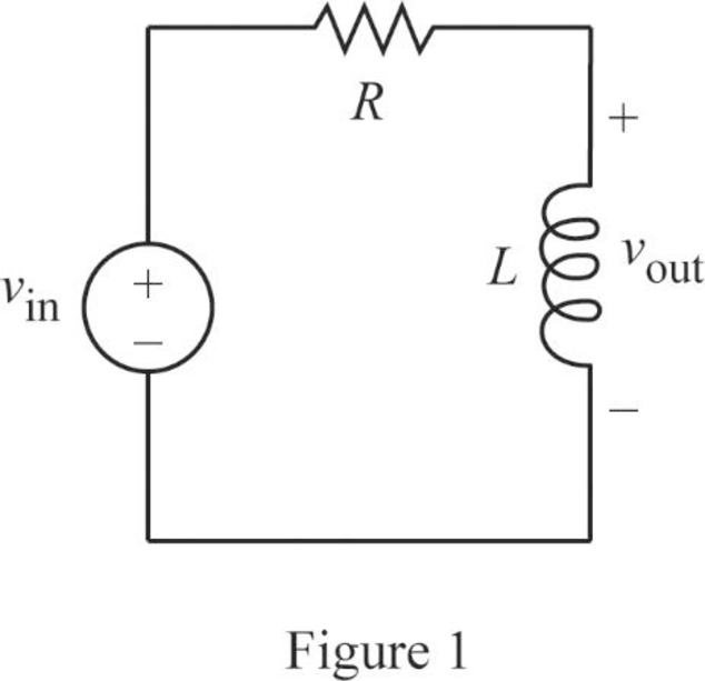
The Figure 1 is redrawn as impedance circuit in Figure 2 using the equations (1) and (2).
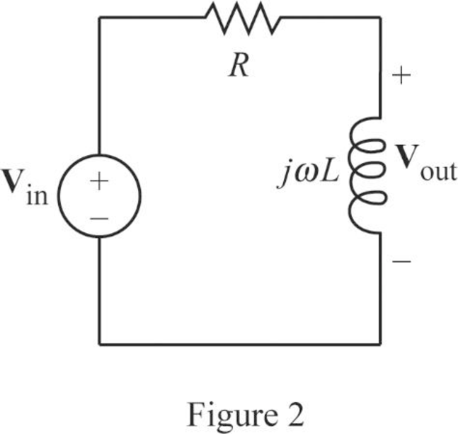
Write the general expression to calculate the transfer function of the circuit in Figure 2.
Here,
Apply Kirchhoff’s voltage law on Figure 2 to find
Rearrange the above equation to find
Substitute
Conclusion:
Thus, the transfer function
(b)
Plot the magnitude and phase as a function of frequency.
Explanation of Solution
Given data:
The value of the resistor
The value of the inductor
Calculation:
From part (a), the transfer function is,
Substitute
Simplify the above equation to find
Re-write the transfer function
From equation (4), the magnitude function of
Write the above equation in decibel (dB).
From equation (4), the phase angle is expressed as follows:
Substitute
Substitute
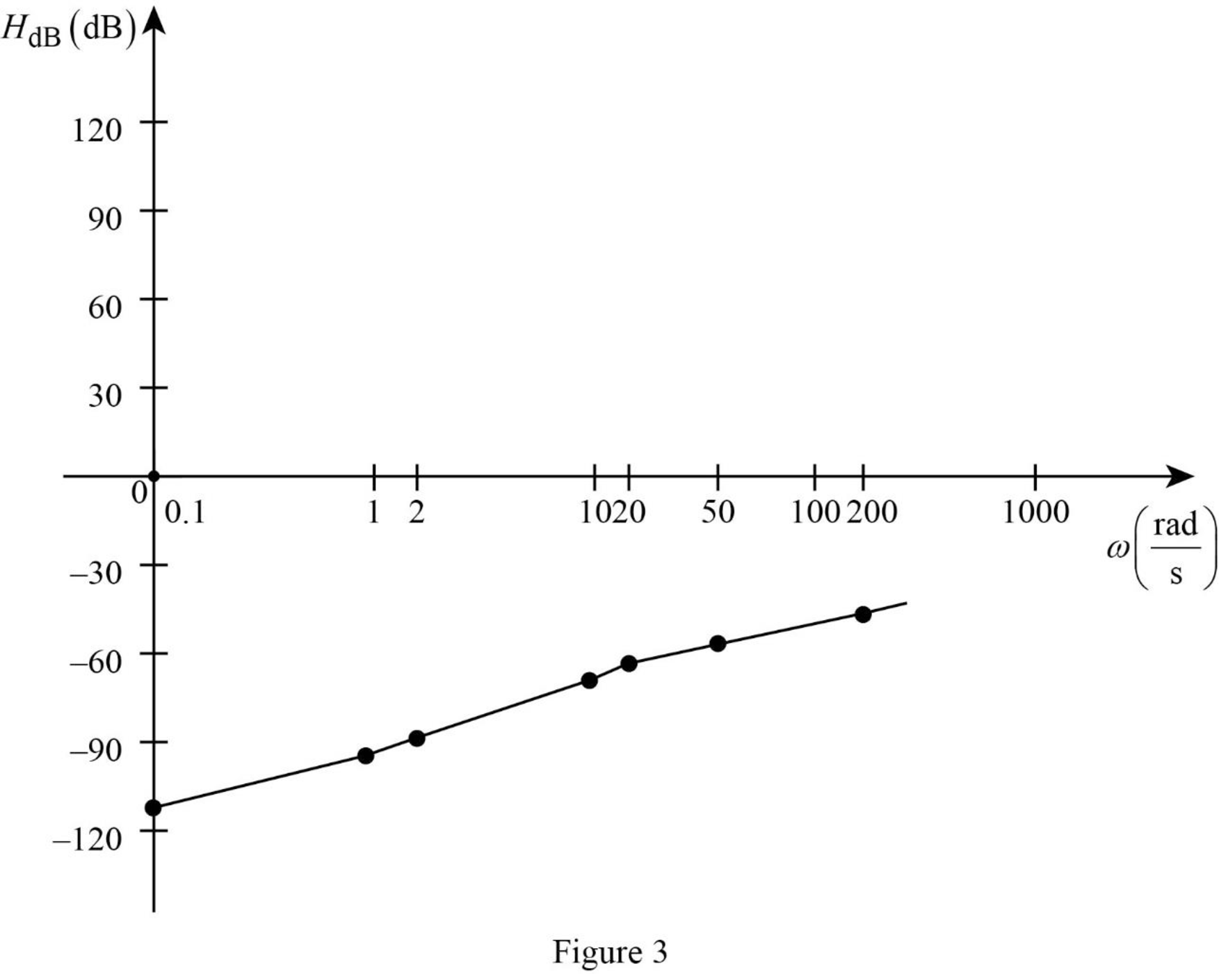
Similarly, by substituting various values for
Table 1
| 0.1 | 1 | 2 | 10 | 20 | 50 | 200 | |
| –112 | –92 | –86 | –72 | –66 | –58 | –46 |
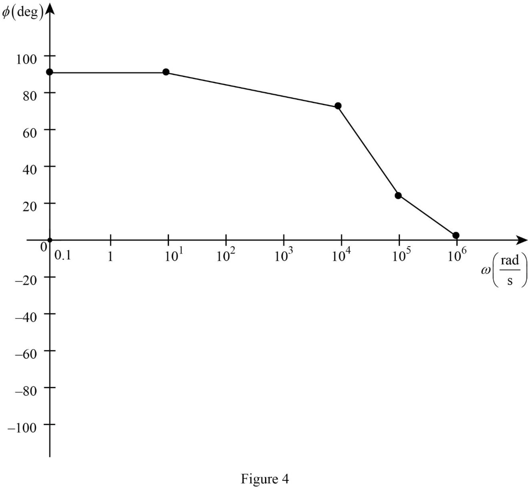
Table 2
| 0.1 | 10 | 104 | 105 | 106 | |
| 90 | 90 | 75.96 | 21.8 | 2.3 |
The Figure 1 is the magnitude plot of the given transfer function obtained using Table 1.
The Figure 2 is the phase plot of the given transfer function obtained using Table 2.
Conclusion:
Thus, the magnitude and phase as a function of frequency is plotted.
(c)
Find the value of the magnitude and phase at a frequency of
Answer to Problem 1E
The value of the magnitude and phase at a frequency of
Explanation of Solution
Given data:
The value of the frequency
Formula used:
Write the expression to calculate the angular frequency.
Here,
Calculation:
From part (a), the transfer function is expressed as,
From equation (7), the magnitude function is expressed as,
Substitute
Substitute
From equation (7), the phase function is expressed as,
Substitute
Substitute
Conclusion:
Thus, the value of the magnitude and phase at a frequency of
Want to see more full solutions like this?
Chapter 15 Solutions
Engineering Circuit Analysis
Additional Engineering Textbook Solutions
Management Information Systems: Managing The Digital Firm (16th Edition)
Starting Out with Java: From Control Structures through Objects (7th Edition) (What's New in Computer Science)
SURVEY OF OPERATING SYSTEMS
Starting Out with Programming Logic and Design (5th Edition) (What's New in Computer Science)
Electric Circuits. (11th Edition)
Concepts Of Programming Languages


- I need help in creating a matlab code to find the currents USING MARTIXS AND INVERSE to find the currentarrow_forwardQuestion 2 A transistor is used as a switch and the waveforms are shown in Figure 2. The parameters are Vcc = 225 V, VBE(sat) = 3 V, IB = 8 A, VCE(sat) = 2 V, Ics = 90 A, td = 0.5 µs, tr = 1 µs, ts = 3 µs, tƒ = 2 μs, and f 10 kHz. The duty cycle is k 50%. The collector- emitter leakage current is ICEO = 2 mA. Determine the power loss due to the collector current: = = = (a) during turn-on ton = td + tr VCE Vcc (b) during conduction period tn V CE(sat) 0 toff" ton Ics 0.9 Ics (c) during turn-off toff = ts + tf (d) during off-time tot (e) the total average power losses PT ICEO 0 IBS 0 Figure 2 V BE(sat) 0 主 * td tr In Is If to iB VBE T= 1/fsarrow_forwardQuestion 1: The beta (B) of the bipolar transistor shown in Figure 1 varies from 12 to 60. The load resistance is Rc = 5. The dc supply voltage is VCC = 40 V and the input voltage to the base circuit is VB = 5 V. If VCE(sat) = 1.2 V, VBE(sat) = 1.6 V, and RB = 0.8 2, calculate: (a) the overdrive factor ODF. (b) the forced ẞ (c) the power loss in the transistor PT. IB VB RB + V BE RC Vcc' Ic + IE Figure 1 VCEarrow_forward
- I need help in creating a matlab code to find the currentsarrow_forwardI need help fixing this MATLAB code: as I try to get it working there were some problems:arrow_forwardI need help in construct a matlab code to find the voltage of VR1 to VR4, the currents, and the watts based on that circuit.arrow_forward
- Q2: Using D flip-flops, design a synchronous counter. The counter counts in the sequence 1,3,5,7, 1,7,5,3,1,3,5,7,.... when its enable input x is equal to 1; otherwise, the counter count 0.arrow_forwardFrom the collector characteristic curves and the dc load line given below, determine the following: (a) Maximum collector current for linear operation (b) Base current at the maximum collector current (c) VCE at maximum collector current. lc (mA) 600 ΜΑ 60- 500 με 50- 400 με 40- 300 μ Α 30- Q-point 200 ΜΑ 20- 10- 100 μ Α 0 VCE (V) 1 2 3 4 5 6 7 8 9 10 [6 Paarrow_forwardProcedure:- 1- Connect the cct. shown in fig.(2). a ADDS DS Fig.(2) 2-For resistive load, measure le output voltage by using oscilloscope ;then sketch this wave. 3- Measure the average values ::f VL and IL: 4- Repeat steps 2 & 3 but for RL load. Report:- 1- Calculate the D.C. output vcl age theoretically and compare it with the test value. 2- Calculate the harmonic cont :nts of the load voltage, and explain how filter components may be selected. 3- Compare between the three-phase half & full-wave uncontrolled bridge rectifier. 4- Draw the waveform for the c:t. shown in fig.(2) but after replaced Di and D3 by thyristors with a 30° and a2 = 90° 5- Draw the waveform for the cct. shown in fig.(2) but after replace the 6-diodes by 6- thyristor. 6- Discuss your results. Please solve No. 4 and 5arrow_forward
- Please I want solution by handwrittenarrow_forward8 00 ! Required information Consider the circuit given below. 0/2 points awarded 3 ΚΩ www t=0 6kM Scored R 1.5i Vc 1 μF 10 V If R = 5.00 kQ, determine vao+). The value of va(0) is 1.4545 V.arrow_forwardI want to know what does it look in a breadboard circuit, because I want to created it but I not sure it is build properly, can you give me an illustuation base on this image, it do need to real, something like virutal examplearrow_forward
 Introductory Circuit Analysis (13th Edition)Electrical EngineeringISBN:9780133923605Author:Robert L. BoylestadPublisher:PEARSON
 Delmar's Standard Textbook Of ElectricityElectrical EngineeringISBN:9781337900348Author:Stephen L. HermanPublisher:Cengage Learning
 Programmable Logic ControllersElectrical EngineeringISBN:9780073373843Author:Frank D. PetruzellaPublisher:McGraw-Hill Education
 Fundamentals of Electric CircuitsElectrical EngineeringISBN:9780078028229Author:Charles K Alexander, Matthew SadikuPublisher:McGraw-Hill Education
 Electric Circuits. (11th Edition)Electrical EngineeringISBN:9780134746968Author:James W. Nilsson, Susan RiedelPublisher:PEARSON
 Engineering ElectromagneticsElectrical EngineeringISBN:9780078028151Author:Hayt, William H. (william Hart), Jr, BUCK, John A.Publisher:Mcgraw-hill Education,