
Engineering Circuit Analysis
9th Edition
ISBN: 9780073545516
Author: Hayt, William H. (william Hart), Jr, Kemmerly, Jack E. (jack Ellsworth), Durbin, Steven M.
Publisher: Mcgraw-hill Education,
expand_more
expand_more
format_list_bulleted
Videos
Textbook Question
Chapter 15.1, Problem 1P
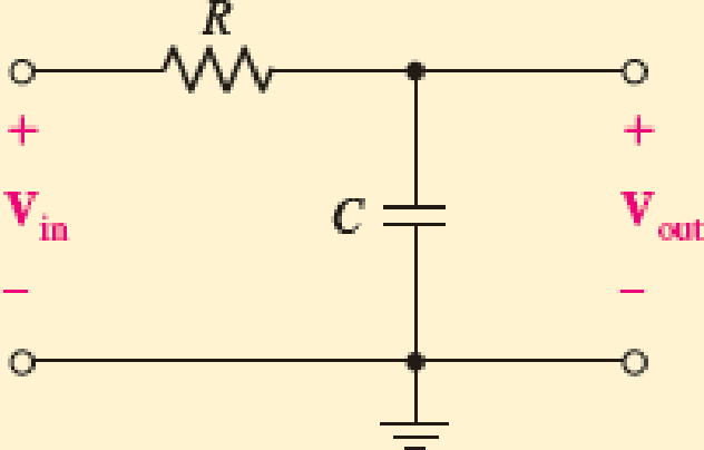
Write an expression for the transfer function of the RC network in Fig 15.1 after switching the positions of the resistor and capacitor such that Vout is now the voltage drop across the resistor. Evaluate at ω = 0, ω = ω0 = 1/CR, and ω = ∞.
FIGURE 15.1 Example RC network, the transfer function of which is of interest.
Expert Solution & Answer
Want to see the full answer?
Check out a sample textbook solution
Students have asked these similar questions
Example2:-
8. = e.A nia +2.1 =
Find the maximum steady-state power capability of a system consisting of a
generator equivalent reactance of 0.4pu connected to an infinite bus through a
series reactance of 1.0 p.u. The terminal voltage of the generator is held at1.10 p.u.
and the voltage of the infinite bus is 1.0 p.u.
B) A 60-Hz generator is supplying 60% of P max to an infinite bus through a reactive network.
A fault occurs which increases the reactance of the network between the generator internal
voltage and the infinite bus by 400%. When the fault is cleared, the maximum power that can
be delivered is 80% of the original maximum value. Determine the critical clearing angle for
the condition described.
In the circuit shown, let Vs-9, R₁-8, R2-2, and R3-4. Use Nodal analysis to determine the current lo. In
particular find:
V2=
10=
A
The relative tolerance for this problem is 5 %.
R₁
V₁
+
ww
R₂
Vs
V₂
21
x
R3
Chapter 15 Solutions
Engineering Circuit Analysis
Ch. 15.1 - Write an expression for the transfer function of...Ch. 15.2 - Calculate HdB at = 146 rad/s if H(s) equals (a)...Ch. 15.2 - Prob. 3PCh. 15.2 - Draw the Bode phase plot for the transfer function...Ch. 15.2 - Construct a Bode magnitude plot for H(s) equal to...Ch. 15.2 - Draw the Bode phase plot for H(s) equal to (a)...Ch. 15.2 - Prob. 7PCh. 15.3 - A parallel resonant circuit is composed of the...Ch. 15.3 - Prob. 9PCh. 15.4 - A marginally high-Q parallel resonant circuit has...
Ch. 15.5 - A series resonant circuit has a bandwidth of 100...Ch. 15.6 - Referring to the circuit of Fig. 15.25a, let R1 =...Ch. 15.6 - Prob. 13PCh. 15.6 - Prob. 14PCh. 15.6 - The series combination of 10 and 10 nF is in...Ch. 15.7 - A parallel resonant circuit is defined by C = 0.01...Ch. 15.8 - Design a high-pass filter with a cutoff frequency...Ch. 15.8 - Design a bandpass filter with a low-frequency...Ch. 15.8 - Design a low-pass filter circuit with a gain of 30...Ch. 15 - For the RL circuit in Fig. 15.52, (a) determine...Ch. 15 - For the RL circuit in Fig. 15.52, switch the...Ch. 15 - Examine the series RLC circuit in Fig. 15.53, with...Ch. 15 - For the circuit in Fig. 15.54, (a) derive an...Ch. 15 - For the circuit in Fig. 15.55, (a) derive an...Ch. 15 - For the circuit in Fig. 15.56, (a) determine the...Ch. 15 - For the circuit in Fig. 15.57, (a) determine the...Ch. 15 - Sketch the Bode magnitude and phase plots for the...Ch. 15 - Use the Bode approach to sketch the magnitude of...Ch. 15 - If a particular network is described by transfer...Ch. 15 - Use MATLAB to plot the magnitude and phase Bode...Ch. 15 - Determine the Bode magnitude plot for the...Ch. 15 - Determine the Bode magnitude and phase plot for...Ch. 15 - Prob. 15ECh. 15 - Prob. 16ECh. 15 - For the circuit of Fig. 15.56, construct a...Ch. 15 - Construct a magnitude and phase Bode plot for the...Ch. 15 - For the circuit in Fig. 15.54, use LTspice to...Ch. 15 - For the circuit in Fig. 15.55, use LTspice to...Ch. 15 - Prob. 21ECh. 15 - A certain parallel RLC circuit is built using...Ch. 15 - A parallel RLC network is constructed using R = 5...Ch. 15 - Prob. 24ECh. 15 - Delete the 2 resistor in the network of Fig....Ch. 15 - Delete the 1 resistor in the network of Fig....Ch. 15 - Prob. 28ECh. 15 - Prob. 29ECh. 15 - Prob. 30ECh. 15 - A parallel RLC network is constructed with a 200 H...Ch. 15 - Prob. 32ECh. 15 - A parallel RLC circuit is constructed such that it...Ch. 15 - Prob. 34ECh. 15 - Prob. 35ECh. 15 - An RLC circuit is constructed using R = 5 , L = 20...Ch. 15 - Prob. 37ECh. 15 - Prob. 38ECh. 15 - For the network of Fig. 15.25a, R1 = 100 , R2 =...Ch. 15 - Assuming an operating frequency of 200 rad/s, find...Ch. 15 - Prob. 41ECh. 15 - Prob. 42ECh. 15 - For the circuit shown in Fig. 15.64, the voltage...Ch. 15 - Prob. 44ECh. 15 - Prob. 45ECh. 15 - Prob. 46ECh. 15 - The filter shown in Fig. 15.66a has the response...Ch. 15 - Prob. 48ECh. 15 - Examine the filter for the circuit in Fig. 15.68....Ch. 15 - Examine the filter for the circuit in Fig. 15.69....Ch. 15 - (a)Design a high-pass filter with a corner...Ch. 15 - (a) Design a low-pass filter with a break...Ch. 15 - Prob. 53ECh. 15 - Prob. 54ECh. 15 - Design a low-pass filter characterized by a...Ch. 15 - Prob. 56ECh. 15 - The circuit in Fig. 15.70 is known as a notch...Ch. 15 - (a) Design a two-stage op amp filter circuit with...Ch. 15 - Design a circuit which removes the entire audio...Ch. 15 - Prob. 61ECh. 15 - If a high-pass filter is required having gain of 6...Ch. 15 - (a) Design a second-order high-pass Butterworth...Ch. 15 - Design a fourth-order high-pass Butterworth filter...Ch. 15 - (a) Design a Sallen-Key low-pass filter with a...Ch. 15 - (a) Design a Sallen-Key low-pass filter with a...Ch. 15 - A piezoelectric sensor has an equivalent circuit...Ch. 15 - Design a parallel resonant circuit for an AM radio...Ch. 15 - The network of Fig. 15.72 was implemented as a...Ch. 15 - Determine the effect of component tolerance on the...
Additional Engineering Textbook Solutions
Find more solutions based on key concepts
What is an uninitialized variable?
Starting Out with Programming Logic and Design (5th Edition) (What's New in Computer Science)
How is the hydrodynamic entry length defined for flow in a pipe? Is the entry length longer in laminar or turbu...
Fluid Mechanics: Fundamentals and Applications
How are relationships between tables expressed in a relational database?
Modern Database Management
The following C++ program will not compile because the lines have been mixed up. cout Success\n; cout Success...
Starting Out with C++ from Control Structures to Objects (9th Edition)
Assume a telephone signal travels through a cable at two-thirds the speed of light. How long does it take the s...
Electric Circuits. (11th Edition)
How does a computers main memory differ from its auxiliary memory?
Java: An Introduction to Problem Solving and Programming (8th Edition)
Knowledge Booster


Learn more about
Need a deep-dive on the concept behind this application? Look no further. Learn more about this topic, electrical-engineering and related others by exploring similar questions and additional content below.Similar questions
- 1. Choose all nodes that must be included, if any, to construct the supernode for Nodal analysis. OV1, V3 OV1, V2 ○ V2, V3 OV1, V2, V4 OV1, V2, V3 O V2, V3, V4 2. Write KCL equation (Nodal equation) at super-node. Write your expression in terms of node voltages V1, V2, V3 and V4 and of the form (G11 V1+G12 V2+G13 V3+G14 V4 = 11), then enter the corresponding values: At super-node KCL: 1/Q G11 1/0 G12 1/Ω G13 1/Q G14 A 3. Use the above equation, the circuit and and super-node inner expression to calculate V3 and then lo : V3= V 10 = R3 Vst + A V₁ + VS2 V₂ V3 w W R₁ R₂ R4 ww R5 V4 V$3arrow_forwardEnter the matrix values (numerical) to solve for voltages at nodes v1, and v2, for the circuit shown, using Nodal equations. In the matrix, row 1, and row 2, correspond to node v1, and node v2 current expressions, respectively. Let Is1=14, Is2=7, R₁=5, R₂-8, R3=2, and R4-5. [G11 G12] [Vi₁ The matrix values are shown here: = G21 G22 [V2] [41] [12] {Hint: As discussed in class and to avoid sign errors, assume nodal currents are locally defined at each node (leaving) and use node labeling as indicated in the circuit. } The relative tolerance for this problem is 5%. VI R2 ww Isl 12 NODE v1 G11 G12 RI 1/Q 1/0 A 4= NODE v2 G21- 1/Q G22 1/0 12 W A === www R3 R4 www Use Cramer's rule (matrix), substitution, or any other method to calculate the voltages: v1 = V v2= V Is2arrow_forwardOnly expert should attemptarrow_forward
- For the circuit shown below, let l₁ = 9, 1₂ = 14, 13= 12, R₁ = 3, R₂ = 8, and R3 = 5. Use nodal equations to determine V1, V2 and I, as follows: • Consider Node 1, obtain a nodal equation in terms of V₁ and V₂ voltages. Simplify your equation to the format 1V1 + b,V₂ = c, then enter the corresponding values of coefficients b₁ and c₁ 1. b₁ =( C₁ = • Now consider Node 2, obtain a second nodal equation in terms of V₁ and V2 voltages. Simplify your equation to the format -1V₁+b2V2=c2 then enter the corresponding values of coefficients b₂ and c₂ 2. (b₂ = value.) ,၄၇ = - 3. Use (1) and (2) to determine V₂ = 4. Determine V₁ 5. Determine | = i 12 V₁ R1 20 www R2 ww I The relative tolerance for this problem is 5%. R3 This is not a decimal or integer www i3arrow_forwardFor the circuit shown, let V1 = 19 V, Vs2 = 76 V, R₁ = 9, R2 = 9, and R3 = 7. Use Nodal analysis to determine the voltage V2 and the current lo, choose the closet values: V2- 4.788 10 = ○ 2.28 11.978 17.761 35.522 23.957 -9.146 8.32 10.173 A O-7.435 O-5.783 10.531 V sl ་ ་ ་ ན ་་་ ་ ་ ་ ་ ་ ་ ་ ་ +1 ww R₁ R₂ ww R3 Io +1 VS2arrow_forwardNO AI PLEASEarrow_forward
- NO AI PLEASEarrow_forwardProblem 4 Consider the following system. In the figure, y(t) denotes the displacement of the mass and u(t) denotes the force applied to the mass. b1 u(t) y(t) + b2 M 0000 0000 K1 K2 a) Find the differential equation model of the system. b) Find the state-space model for the system. Write x, A, B, C and D clearly in your answer.arrow_forwardNO AI PLEASEarrow_forward
- Not use ai pleasearrow_forwardShow workarrow_forwardProblem 1 (a) Suppose the Laplace transform of a causal signal x₁ (t) is given by S X₁(s) = 52 +2 Using the Laplace transform properties, find the Laplace transform of the following signal x2(t). x2(t) = e2t+1 x₁(t − 1) - tx₁(2t - 1) (b) Suppose an LTI system T whose impulse response is given by h(t) e 2t 1(t) t 1(t) +28(t) What is the transfer function of the system? (c) If the input x2 (t) is applied to the system T, what will be the output Y₂(s)? Note, you just need to provide Laplace transform of the output y₂(t). Simplification is not needed in any part of this question.arrow_forward
arrow_back_ios
SEE MORE QUESTIONS
arrow_forward_ios
Recommended textbooks for you
 Introductory Circuit Analysis (13th Edition)Electrical EngineeringISBN:9780133923605Author:Robert L. BoylestadPublisher:PEARSON
 Delmar's Standard Textbook Of ElectricityElectrical EngineeringISBN:9781337900348Author:Stephen L. HermanPublisher:Cengage Learning
 Programmable Logic ControllersElectrical EngineeringISBN:9780073373843Author:Frank D. PetruzellaPublisher:McGraw-Hill Education
 Fundamentals of Electric CircuitsElectrical EngineeringISBN:9780078028229Author:Charles K Alexander, Matthew SadikuPublisher:McGraw-Hill Education
 Electric Circuits. (11th Edition)Electrical EngineeringISBN:9780134746968Author:James W. Nilsson, Susan RiedelPublisher:PEARSON
 Engineering ElectromagneticsElectrical EngineeringISBN:9780078028151Author:Hayt, William H. (william Hart), Jr, BUCK, John A.Publisher:Mcgraw-hill Education,
Introductory Circuit Analysis (13th Edition)
Electrical Engineering
ISBN:9780133923605
Author:Robert L. Boylestad
Publisher:PEARSON
Delmar's Standard Textbook Of Electricity
Electrical Engineering
ISBN:9781337900348
Author:Stephen L. Herman
Publisher:Cengage Learning
Programmable Logic Controllers
Electrical Engineering
ISBN:9780073373843
Author:Frank D. Petruzella
Publisher:McGraw-Hill Education
Fundamentals of Electric Circuits
Electrical Engineering
ISBN:9780078028229
Author:Charles K Alexander, Matthew Sadiku
Publisher:McGraw-Hill Education
Electric Circuits. (11th Edition)
Electrical Engineering
ISBN:9780134746968
Author:James W. Nilsson, Susan Riedel
Publisher:PEARSON
Engineering Electromagnetics
Electrical Engineering
ISBN:9780078028151
Author:Hayt, William H. (william Hart), Jr, BUCK, John A.
Publisher:Mcgraw-hill Education,
David Sarnoff, Howard Armstrong & the Superheterodyne Receiver; Author: Kathy Loves Physics & History;https://www.youtube.com/watch?v=7eTfF67Ka5w;License: Standard Youtube License