
Engineering Circuit Analysis
9th Edition
ISBN: 9780073545516
Author: Hayt, William H. (william Hart), Jr, Kemmerly, Jack E. (jack Ellsworth), Durbin, Steven M.
Publisher: Mcgraw-hill Education,
expand_more
expand_more
format_list_bulleted
Concept explainers
Videos
Textbook Question
Chapter 15, Problem 49E
Examine the filter for the circuit in Fig. 15.68. (a) Without going through a full mathematical analysis of the circuit, determine what kind of filter this is. (b) Determine an expression for the transfer function H(s) = vout/vin. (c) Use MATLAB to construct a Bode plot (with frequency in Hz) for R1 = R2 = 50 Ω, C1 = 50 nF, C2 = 225 nF, L1 = 563 μH, and L2 = 125 μH.
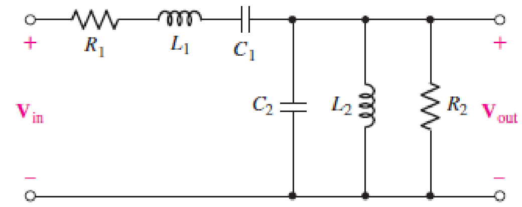
■ FIGURE 15.68
Expert Solution & Answer
Want to see the full answer?
Check out a sample textbook solution
Students have asked these similar questions
2. (35 points) Use you program to investigative properties of a four step linear pathway. Just
extend the model given in question 1 to include an additional two species x2 and x3. You can
assume simple irreversible mass-action kinetic on each reaction.
I recommend you use the following values for the rate constants: 1 = 0.6; k2 = 1.8; k3 =
0.5; k40.04. This will enable you to more easily answer the following questions.
You can also assume that the input is the source X and you can set its value to one.
You may find that the plot of the phase change at x3 is broken at -180 degrees because it wraps
around. To avoid this you can use the method:
phase = np.unwrap(phase)
to make sure the phase plot is continuous.
[10] i) Compute and show the Bode plots for x1, x2 and x3 with respect to the input Xo.
[5] ii) Do you see a pattern with the maximum phase shifts as you move from x₁ to x3?
[10] iii) Can you explain this pattern?
[5] iv) What would you predict would be the maximum phase shift for…
Please answer all
The zombies showed up while you were sleeping! The zombie alarm you built goes off as they open the door. You jolt awake to see an alpha-zombie charging through the door. The alphas are zombies that turned all of the zombies in its army. If you can take down this one zombie, all the others pouring into the room should fall as well. Luckily, your group was prepared for this eventuality. Another member of your team has constructed the zombie shocker circuit shown in Figure 5, using some batteries for the voltage source, some rusty metal for the resistors and a coil of wire for the inductor. The switch is just you pulling apart two wires to open the circuit (while holding them by their insulated sheaths).
1. Construct the circuit shown in Figure 15 in the Circuit JS simulator. 2. Start the simulation with switch SW1 in the closed position. You’ve been charging this circuit all night, so you’ll want to let the circuit run for a while (roughly 30 seconds at max…
Please answer all questions
1. Calculate the values of the following without using Circuit JS. Assume the circuit has reached steady state. Show these calculations: a) Voltage across and current through C1. b) Voltage across and current through L1. c) Voltage across and current through R5. 2. Construct the circuit in the Circuit JS simulator [1]. 3. Perform a simulation and determine the following values. Record them. Allow the circuit to reach steady state. a) Voltage across and current through C1. b) Voltage across and current through L1. c) Voltage across and current through R5. 4. Include a screen shot of the simulator window (including showing the values listed above). 5. Answer the following questions: a) In a DC circuit, what does a capacitor look like?
b) In a DC circuit, what does an inductor look like?
Chapter 15 Solutions
Engineering Circuit Analysis
Ch. 15.1 - Write an expression for the transfer function of...Ch. 15.2 - Calculate HdB at = 146 rad/s if H(s) equals (a)...Ch. 15.2 - Prob. 3PCh. 15.2 - Draw the Bode phase plot for the transfer function...Ch. 15.2 - Construct a Bode magnitude plot for H(s) equal to...Ch. 15.2 - Draw the Bode phase plot for H(s) equal to (a)...Ch. 15.2 - Prob. 7PCh. 15.3 - A parallel resonant circuit is composed of the...Ch. 15.3 - Prob. 9PCh. 15.4 - A marginally high-Q parallel resonant circuit has...
Ch. 15.5 - A series resonant circuit has a bandwidth of 100...Ch. 15.6 - Referring to the circuit of Fig. 15.25a, let R1 =...Ch. 15.6 - Prob. 13PCh. 15.6 - Prob. 14PCh. 15.6 - The series combination of 10 and 10 nF is in...Ch. 15.7 - A parallel resonant circuit is defined by C = 0.01...Ch. 15.8 - Design a high-pass filter with a cutoff frequency...Ch. 15.8 - Design a bandpass filter with a low-frequency...Ch. 15.8 - Design a low-pass filter circuit with a gain of 30...Ch. 15 - For the RL circuit in Fig. 15.52, (a) determine...Ch. 15 - For the RL circuit in Fig. 15.52, switch the...Ch. 15 - Examine the series RLC circuit in Fig. 15.53, with...Ch. 15 - For the circuit in Fig. 15.54, (a) derive an...Ch. 15 - For the circuit in Fig. 15.55, (a) derive an...Ch. 15 - For the circuit in Fig. 15.56, (a) determine the...Ch. 15 - For the circuit in Fig. 15.57, (a) determine the...Ch. 15 - Sketch the Bode magnitude and phase plots for the...Ch. 15 - Use the Bode approach to sketch the magnitude of...Ch. 15 - If a particular network is described by transfer...Ch. 15 - Use MATLAB to plot the magnitude and phase Bode...Ch. 15 - Determine the Bode magnitude plot for the...Ch. 15 - Determine the Bode magnitude and phase plot for...Ch. 15 - Prob. 15ECh. 15 - Prob. 16ECh. 15 - For the circuit of Fig. 15.56, construct a...Ch. 15 - Construct a magnitude and phase Bode plot for the...Ch. 15 - For the circuit in Fig. 15.54, use LTspice to...Ch. 15 - For the circuit in Fig. 15.55, use LTspice to...Ch. 15 - Prob. 21ECh. 15 - A certain parallel RLC circuit is built using...Ch. 15 - A parallel RLC network is constructed using R = 5...Ch. 15 - Prob. 24ECh. 15 - Delete the 2 resistor in the network of Fig....Ch. 15 - Delete the 1 resistor in the network of Fig....Ch. 15 - Prob. 28ECh. 15 - Prob. 29ECh. 15 - Prob. 30ECh. 15 - A parallel RLC network is constructed with a 200 H...Ch. 15 - Prob. 32ECh. 15 - A parallel RLC circuit is constructed such that it...Ch. 15 - Prob. 34ECh. 15 - Prob. 35ECh. 15 - An RLC circuit is constructed using R = 5 , L = 20...Ch. 15 - Prob. 37ECh. 15 - Prob. 38ECh. 15 - For the network of Fig. 15.25a, R1 = 100 , R2 =...Ch. 15 - Assuming an operating frequency of 200 rad/s, find...Ch. 15 - Prob. 41ECh. 15 - Prob. 42ECh. 15 - For the circuit shown in Fig. 15.64, the voltage...Ch. 15 - Prob. 44ECh. 15 - Prob. 45ECh. 15 - Prob. 46ECh. 15 - The filter shown in Fig. 15.66a has the response...Ch. 15 - Prob. 48ECh. 15 - Examine the filter for the circuit in Fig. 15.68....Ch. 15 - Examine the filter for the circuit in Fig. 15.69....Ch. 15 - (a)Design a high-pass filter with a corner...Ch. 15 - (a) Design a low-pass filter with a break...Ch. 15 - Prob. 53ECh. 15 - Prob. 54ECh. 15 - Design a low-pass filter characterized by a...Ch. 15 - Prob. 56ECh. 15 - The circuit in Fig. 15.70 is known as a notch...Ch. 15 - (a) Design a two-stage op amp filter circuit with...Ch. 15 - Design a circuit which removes the entire audio...Ch. 15 - Prob. 61ECh. 15 - If a high-pass filter is required having gain of 6...Ch. 15 - (a) Design a second-order high-pass Butterworth...Ch. 15 - Design a fourth-order high-pass Butterworth filter...Ch. 15 - (a) Design a Sallen-Key low-pass filter with a...Ch. 15 - (a) Design a Sallen-Key low-pass filter with a...Ch. 15 - A piezoelectric sensor has an equivalent circuit...Ch. 15 - Design a parallel resonant circuit for an AM radio...Ch. 15 - The network of Fig. 15.72 was implemented as a...Ch. 15 - Determine the effect of component tolerance on the...
Additional Engineering Textbook Solutions
Find more solutions based on key concepts
This optional Google account security feature sends you a message with a code that you must enter, in addition ...
SURVEY OF OPERATING SYSTEMS
Why is the study of database technology important?
Database Concepts (8th Edition)
Assume a telephone signal travels through a cable at two-thirds the speed of light. How long does it take the s...
Electric Circuits. (11th Edition)
17–1C A high-speed aircraft is cruising in still air. How does the temperature of air at the nose of the aircra...
Thermodynamics: An Engineering Approach
The solid steel shaft AC has a diameter of 25 mm and is supported by smooth bearings at D and E. It is coupled ...
Mechanics of Materials (10th Edition)
What types of coolant are used in vehicles?
Automotive Technology: Principles, Diagnosis, And Service (6th Edition) (halderman Automotive Series)
Knowledge Booster


Learn more about
Need a deep-dive on the concept behind this application? Look no further. Learn more about this topic, electrical-engineering and related others by exploring similar questions and additional content below.Similar questions
- Help with homework, with the extra portion part too pleasearrow_forwardRedraw the previous circuit and add a 24 V red lamp to indicate the relay coil is on, a 230 V yellow lamp to indicate the solenoid is on, green lamp to indicate the solenoid is off. Use only one relay, which has multiple contacts.arrow_forwardDesign a control circuit so a 24 V relay , start button, and a stop push button (on/off with memory) operates an electromechanical relay to control a 230 V solenoid Next, Redraw the previous circuit and add a 24 V red lamp to indicate the relay coil is on, a 230 V yellow lamp to indicate the solenoid is on, green lamp to indicate the solenoid is off. Use only one relay, which has multiple contacts.arrow_forward
- please answer it handwritten , thanks! will give thumbs uparrow_forwardEXAMPLE 6.3 Suppose the Fourier transform of a pulse is as follows: (1-a) Ть. 2Ть H(f) = < α (To) (-Tof+ 1 +a (1-a) (1+α) ·<|f|≤· 2 2ть 2Ть (1+α) 0, <\f\ 2Ть where 0≤a≤1. Show that this pulse in both time and frequency domains satisfies the Nyquist criterion.arrow_forwardIn matlabarrow_forward
- not use ai pleasearrow_forwardIn matlabarrow_forwardEXAMPLE 4.4 In a binary symmetric communication (BSC) channel, the input bits transmitted over the channel are either 0 or 1 with probabilities p and 1-p, respectively. Due to channel noise, errors are made. As shown in Figure 4.4, the channel is assumed to be symmetric, which means the probability of receiving 1 when 0 is transmitted is the same as the probability of receiving 0 when 1 is transmit- ted. The conditional probabilities of error are assumed to be each e. Determine the average prob- ability of error, also known as the bit error rate, as well as the a posteriori probabilities.arrow_forward
- What is the bandwidth requirement in Hz for baseband binary transmission at 64 kbps, if the roll-off factor is 0.25?arrow_forwardEXAMPLE 6.4 Suppose the roll-off factor is 25% and the bandwidth of a baseband transmission system satisfying the Nyquist criterion is 30 kHz. Determine the bit rate. Solution 1+α 1arrow_forwardEXAMPLE 4.9 In a communication system, the noise level is modeled as a Gaussian random variable with m=0 and ² = 0.0001. Determine P(X > 0.01) and P(-0.04 ≤x≤ 0.05). 3arrow_forward
arrow_back_ios
SEE MORE QUESTIONS
arrow_forward_ios
Recommended textbooks for you
 Introductory Circuit Analysis (13th Edition)Electrical EngineeringISBN:9780133923605Author:Robert L. BoylestadPublisher:PEARSON
 Delmar's Standard Textbook Of ElectricityElectrical EngineeringISBN:9781337900348Author:Stephen L. HermanPublisher:Cengage Learning
 Programmable Logic ControllersElectrical EngineeringISBN:9780073373843Author:Frank D. PetruzellaPublisher:McGraw-Hill Education
 Fundamentals of Electric CircuitsElectrical EngineeringISBN:9780078028229Author:Charles K Alexander, Matthew SadikuPublisher:McGraw-Hill Education
 Electric Circuits. (11th Edition)Electrical EngineeringISBN:9780134746968Author:James W. Nilsson, Susan RiedelPublisher:PEARSON
 Engineering ElectromagneticsElectrical EngineeringISBN:9780078028151Author:Hayt, William H. (william Hart), Jr, BUCK, John A.Publisher:Mcgraw-hill Education,
Introductory Circuit Analysis (13th Edition)
Electrical Engineering
ISBN:9780133923605
Author:Robert L. Boylestad
Publisher:PEARSON
Delmar's Standard Textbook Of Electricity
Electrical Engineering
ISBN:9781337900348
Author:Stephen L. Herman
Publisher:Cengage Learning
Programmable Logic Controllers
Electrical Engineering
ISBN:9780073373843
Author:Frank D. Petruzella
Publisher:McGraw-Hill Education
Fundamentals of Electric Circuits
Electrical Engineering
ISBN:9780078028229
Author:Charles K Alexander, Matthew Sadiku
Publisher:McGraw-Hill Education
Electric Circuits. (11th Edition)
Electrical Engineering
ISBN:9780134746968
Author:James W. Nilsson, Susan Riedel
Publisher:PEARSON
Engineering Electromagnetics
Electrical Engineering
ISBN:9780078028151
Author:Hayt, William H. (william Hart), Jr, BUCK, John A.
Publisher:Mcgraw-hill Education,
What is Filter & Classification of Filters | Four Types of Filters | Electronic Devices & Circuits; Author: SimplyInfo;https://www.youtube.com/watch?v=9x1Sjz-VPSg;License: Standard Youtube License