
Engineering Circuit Analysis
9th Edition
ISBN: 9780073545516
Author: Hayt, William H. (william Hart), Jr, Kemmerly, Jack E. (jack Ellsworth), Durbin, Steven M.
Publisher: Mcgraw-hill Education,
expand_more
expand_more
format_list_bulleted
Videos
Textbook Question
Chapter 15, Problem 47E
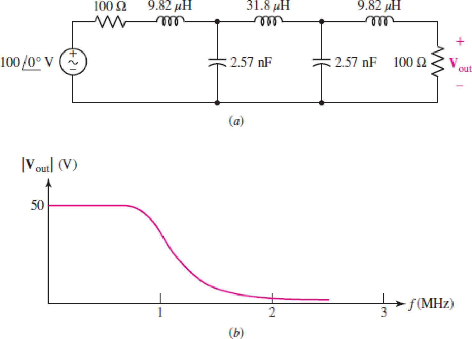
The filter shown in Fig. 15.66a has the response curve shown in Fig. 15.66b. (a) Scale the filter so that it operates between a 50 Ω source and a 50 Ω load and has a cutoff frequency of 20 kHz. (b) Draw the new response curve.
Expert Solution & Answer
Want to see the full answer?
Check out a sample textbook solution
Students have asked these similar questions
I need help in construct a method in matlab to find the voltage of VR1 to VR4, rhe current, and the power base on that circuit
Nominal or Theortical:
E1 = 3V , E2 = 9V, E3 = 1.5V
R1 =10Kohm, R2 =2Kohm, R3 =1Kohm, R4 =16Kohm
Procedure:-
1- Connect the cct. shown in fig.(2).
a
ADDs Ds
Fig.(2)
2-For resistive load, measure le output voltage by using oscilloscope; then sketch this
wave.
3- Measure the average values f VL and IL:
4- Repeat steps 2 & 3 but for RL load.
Report:-
1- Calculate the D.C. output vcl age theoretically and compare it with the test value.
2- Calculate the harmonic cont :nts of the load voltage, and explain how filter
components may be selected.
3- Compare between the three-phase half & full-wave uncontrolled bridge rectifier.
4- Draw the waveform for the c:t. shown in fig.(2) but after replaced Di and D3 by
thyristors with a = 30° and a2 = 90°
5- Draw the waveform for the cct. shown in fig.(2) but after replace the 6-diodes by 6-
thyristor.
6- Discuss your results. Draw the waves on graph paper
please
Please solve No. 4
and 5
not use ai please
chat gpt
How to draw this in LtSpice
Chapter 15 Solutions
Engineering Circuit Analysis
Ch. 15.1 - Write an expression for the transfer function of...Ch. 15.2 - Calculate HdB at = 146 rad/s if H(s) equals (a)...Ch. 15.2 - Prob. 3PCh. 15.2 - Draw the Bode phase plot for the transfer function...Ch. 15.2 - Construct a Bode magnitude plot for H(s) equal to...Ch. 15.2 - Draw the Bode phase plot for H(s) equal to (a)...Ch. 15.2 - Prob. 7PCh. 15.3 - A parallel resonant circuit is composed of the...Ch. 15.3 - Prob. 9PCh. 15.4 - A marginally high-Q parallel resonant circuit has...
Ch. 15.5 - A series resonant circuit has a bandwidth of 100...Ch. 15.6 - Referring to the circuit of Fig. 15.25a, let R1 =...Ch. 15.6 - Prob. 13PCh. 15.6 - Prob. 14PCh. 15.6 - The series combination of 10 and 10 nF is in...Ch. 15.7 - A parallel resonant circuit is defined by C = 0.01...Ch. 15.8 - Design a high-pass filter with a cutoff frequency...Ch. 15.8 - Design a bandpass filter with a low-frequency...Ch. 15.8 - Design a low-pass filter circuit with a gain of 30...Ch. 15 - For the RL circuit in Fig. 15.52, (a) determine...Ch. 15 - For the RL circuit in Fig. 15.52, switch the...Ch. 15 - Examine the series RLC circuit in Fig. 15.53, with...Ch. 15 - For the circuit in Fig. 15.54, (a) derive an...Ch. 15 - For the circuit in Fig. 15.55, (a) derive an...Ch. 15 - For the circuit in Fig. 15.56, (a) determine the...Ch. 15 - For the circuit in Fig. 15.57, (a) determine the...Ch. 15 - Sketch the Bode magnitude and phase plots for the...Ch. 15 - Use the Bode approach to sketch the magnitude of...Ch. 15 - If a particular network is described by transfer...Ch. 15 - Use MATLAB to plot the magnitude and phase Bode...Ch. 15 - Determine the Bode magnitude plot for the...Ch. 15 - Determine the Bode magnitude and phase plot for...Ch. 15 - Prob. 15ECh. 15 - Prob. 16ECh. 15 - For the circuit of Fig. 15.56, construct a...Ch. 15 - Construct a magnitude and phase Bode plot for the...Ch. 15 - For the circuit in Fig. 15.54, use LTspice to...Ch. 15 - For the circuit in Fig. 15.55, use LTspice to...Ch. 15 - Prob. 21ECh. 15 - A certain parallel RLC circuit is built using...Ch. 15 - A parallel RLC network is constructed using R = 5...Ch. 15 - Prob. 24ECh. 15 - Delete the 2 resistor in the network of Fig....Ch. 15 - Delete the 1 resistor in the network of Fig....Ch. 15 - Prob. 28ECh. 15 - Prob. 29ECh. 15 - Prob. 30ECh. 15 - A parallel RLC network is constructed with a 200 H...Ch. 15 - Prob. 32ECh. 15 - A parallel RLC circuit is constructed such that it...Ch. 15 - Prob. 34ECh. 15 - Prob. 35ECh. 15 - An RLC circuit is constructed using R = 5 , L = 20...Ch. 15 - Prob. 37ECh. 15 - Prob. 38ECh. 15 - For the network of Fig. 15.25a, R1 = 100 , R2 =...Ch. 15 - Assuming an operating frequency of 200 rad/s, find...Ch. 15 - Prob. 41ECh. 15 - Prob. 42ECh. 15 - For the circuit shown in Fig. 15.64, the voltage...Ch. 15 - Prob. 44ECh. 15 - Prob. 45ECh. 15 - Prob. 46ECh. 15 - The filter shown in Fig. 15.66a has the response...Ch. 15 - Prob. 48ECh. 15 - Examine the filter for the circuit in Fig. 15.68....Ch. 15 - Examine the filter for the circuit in Fig. 15.69....Ch. 15 - (a)Design a high-pass filter with a corner...Ch. 15 - (a) Design a low-pass filter with a break...Ch. 15 - Prob. 53ECh. 15 - Prob. 54ECh. 15 - Design a low-pass filter characterized by a...Ch. 15 - Prob. 56ECh. 15 - The circuit in Fig. 15.70 is known as a notch...Ch. 15 - (a) Design a two-stage op amp filter circuit with...Ch. 15 - Design a circuit which removes the entire audio...Ch. 15 - Prob. 61ECh. 15 - If a high-pass filter is required having gain of 6...Ch. 15 - (a) Design a second-order high-pass Butterworth...Ch. 15 - Design a fourth-order high-pass Butterworth filter...Ch. 15 - (a) Design a Sallen-Key low-pass filter with a...Ch. 15 - (a) Design a Sallen-Key low-pass filter with a...Ch. 15 - A piezoelectric sensor has an equivalent circuit...Ch. 15 - Design a parallel resonant circuit for an AM radio...Ch. 15 - The network of Fig. 15.72 was implemented as a...Ch. 15 - Determine the effect of component tolerance on the...
Additional Engineering Textbook Solutions
Find more solutions based on key concepts
3.3 It is known that a vertical force of 200 lb is required to remove the nail at C from the board. As the nail...
Vector Mechanics for Engineers: Statics
Consider the adage Never ask a question for which you do not want the answer. a. Is following that adage ethica...
Experiencing MIS
The solid steel shaft AC has a diameter of 25 mm and is supported by smooth bearings at D and E. It is coupled ...
Mechanics of Materials (10th Edition)
This optional Google account security feature sends you a message with a code that you must enter, in addition ...
SURVEY OF OPERATING SYSTEMS
Computers process data under the control of sets of instructions called
Java How to Program, Early Objects (11th Edition) (Deitel: How to Program)
What is an uninitialized variable?
Starting Out with Programming Logic and Design (5th Edition) (What's New in Computer Science)
Knowledge Booster


Learn more about
Need a deep-dive on the concept behind this application? Look no further. Learn more about this topic, electrical-engineering and related others by exploring similar questions and additional content below.Similar questions
- 4. Discussion: Compare between theoretical effect of KI at first order and second order systems regarding steady-state errors and transient responses with the practical In Experiment Integral Controllerarrow_forwardI would appreciate your help in solving the questions and drawing.arrow_forward498 FET AMPLIFIERS AND SWITCHING CIRCUITS FIGURE 9-54 FIGURE 0.55 5. Identify the type of FET and its bias arrangement in Figure 9-54. Ideally, what is Vas? 6. Calculate the dc voltages from each terminal to ground for the FETs in Figure 9-54. +15 V -10 V +12 V 8 mA Ro 3 mA 1.0 ΚΩ Rp 1.5 ΚΩ Rp 6 mA R₁ 1.0 ΚΩ 10 ΚΩ RG * 10 ΜΩ RG 10 ΜΩ ww Rs R₂ • 330 Ω · 4.7 ΚΩ (a) (b) 7. Identify each characteristic curve in Figure 9-55 by the type of FET that it represents.arrow_forward
- Can you help me achieve the requirements using Arduino? I have encountered some issues with these requirements. 1. Functionality:** The system must control 3 LEDS (Red, Green, and Blue) to produce at least 4 different lighting modes: a. **Mode 1: All LEDs blink simultaneously at 1-second intervals. b. Mode 2: LEDs blink in sequence (Red → Green → Blue) with a 500ms delay between each LED. c. **Mode 3:** LEDs fade in and out smoothly (PWM control) in the order Red Green → Blue. d. **Mode 4: Custom mode (e.g., random blinking or a pattern of your choice). 2. Constraints:** -Use only one push button to cycle through the modes. -The system must operate within a 5V power supply. -The total current drawn by the LEDs must not exceed 100mA. -Use resistors to limit the current through each LED appropriately. 3. Design Process:** -Analysis: Calculate the required resistor values for each LED to ensure they operate within their specified current limits. Synthesis: Develop a circuit schematic and…arrow_forwardnot use ai pleasearrow_forwardProcedure:- 1- Connect the cct. shown in fig.(2). a ADDS DS Fig.(2) 2-For resistive load, measure le output voltage by using oscilloscope ;then sketch this wave. 3- Measure the average values ::f VL and IL: 4- Repeat steps 2 & 3 but for RL load. Report:- 1- Calculate the D.C. output vcl age theoretically and compare it with the test value. 2- Calculate the harmonic cont :nts of the load voltage, and explain how filter components may be selected. 3- Compare between the three-phase half & full-wave uncontrolled bridge rectifier. 4- Draw the waveform for the c:t. shown in fig.(2) but after replaced Di and D3 by thyristors with a 30° and a2 = 90° 5- Draw the waveform for the cct. shown in fig.(2) but after replace the 6-diodes by 6- thyristor. 6- Discuss your results. Please solve No. 4 and 5arrow_forward
- a.) Sketch each of the following signals, and starting with the defining relation, finds its Fourier transform X (w) - a) x(t) = rect(t − 3) b) x(t)=3t rect(t) c) x(t) = 2te 3u1(t) d) x(t) = e−2|t| b.) Sketch the magnitude and phase spectrum for the four signals in Problem (a). c) Calculate energy using time-domain and frequency domain formulas for signals in Problem (a) and (b). Confirm Parseval's theorem using these calculations.arrow_forwardI need help in construct a method in matlab to find the voltage of VR1 to VR4, rhe current, and the power base on that circuit Nominal or Theortical: E1 = 3V , E2 = 9V, E3 = 1.5V R1 =10Kohm, R2 =2Kohm, R3 =1Kohm, R4 =16Kohmarrow_forwardI have a question based on the mesh anaylsis, why does current around R1 and the same as R3?arrow_forward
- 1. Compute the output signals S and T for the circuit. Input signals P = 1, Q = 1, and R = 1. C₁ P half-adder #1 R AND -S C₁₂ half-adder #2 2. Use 8-bit representations to compute the following sum. Show all work. 57+(-118) 3. Find a counterexample to show that the following statement is false: 1 Vx Є R, x>- χ T 4. Is the proposed negation correct? If yes, provide a sound reasoning. If not, provide a sound reasoning and write the correct negation. Statement: For all integers n, if n² is even then n is even. Negation: For all integers n, if n² is even then n is not even.arrow_forwardnot use aiarrow_forward2. (35 points) Use you program to investigative properties of a four step linear pathway. Just extend the model given in question 1 to include an additional two species x2 and x3. You can assume simple irreversible mass-action kinetic on each reaction. I recommend you use the following values for the rate constants: 1 = 0.6; k2 = 1.8; k3 = 0.5; k40.04. This will enable you to more easily answer the following questions. You can also assume that the input is the source X and you can set its value to one. You may find that the plot of the phase change at x3 is broken at -180 degrees because it wraps around. To avoid this you can use the method: phase = np.unwrap(phase) to make sure the phase plot is continuous. [10] i) Compute and show the Bode plots for x1, x2 and x3 with respect to the input Xo. [5] ii) Do you see a pattern with the maximum phase shifts as you move from x₁ to x3? [10] iii) Can you explain this pattern? [5] iv) What would you predict would be the maximum phase shift for…arrow_forward
arrow_back_ios
SEE MORE QUESTIONS
arrow_forward_ios
Recommended textbooks for you
 Introductory Circuit Analysis (13th Edition)Electrical EngineeringISBN:9780133923605Author:Robert L. BoylestadPublisher:PEARSON
 Delmar's Standard Textbook Of ElectricityElectrical EngineeringISBN:9781337900348Author:Stephen L. HermanPublisher:Cengage Learning
 Programmable Logic ControllersElectrical EngineeringISBN:9780073373843Author:Frank D. PetruzellaPublisher:McGraw-Hill Education
 Fundamentals of Electric CircuitsElectrical EngineeringISBN:9780078028229Author:Charles K Alexander, Matthew SadikuPublisher:McGraw-Hill Education
 Electric Circuits. (11th Edition)Electrical EngineeringISBN:9780134746968Author:James W. Nilsson, Susan RiedelPublisher:PEARSON
 Engineering ElectromagneticsElectrical EngineeringISBN:9780078028151Author:Hayt, William H. (william Hart), Jr, BUCK, John A.Publisher:Mcgraw-hill Education,
Introductory Circuit Analysis (13th Edition)
Electrical Engineering
ISBN:9780133923605
Author:Robert L. Boylestad
Publisher:PEARSON
Delmar's Standard Textbook Of Electricity
Electrical Engineering
ISBN:9781337900348
Author:Stephen L. Herman
Publisher:Cengage Learning
Programmable Logic Controllers
Electrical Engineering
ISBN:9780073373843
Author:Frank D. Petruzella
Publisher:McGraw-Hill Education
Fundamentals of Electric Circuits
Electrical Engineering
ISBN:9780078028229
Author:Charles K Alexander, Matthew Sadiku
Publisher:McGraw-Hill Education
Electric Circuits. (11th Edition)
Electrical Engineering
ISBN:9780134746968
Author:James W. Nilsson, Susan Riedel
Publisher:PEARSON
Engineering Electromagnetics
Electrical Engineering
ISBN:9780078028151
Author:Hayt, William H. (william Hart), Jr, BUCK, John A.
Publisher:Mcgraw-hill Education,
Pressure Sensors with Display; Author: Balluff Worldwide;https://www.youtube.com/watch?v=HqAV2xjCLxE;License: Standard Youtube License