
Videos
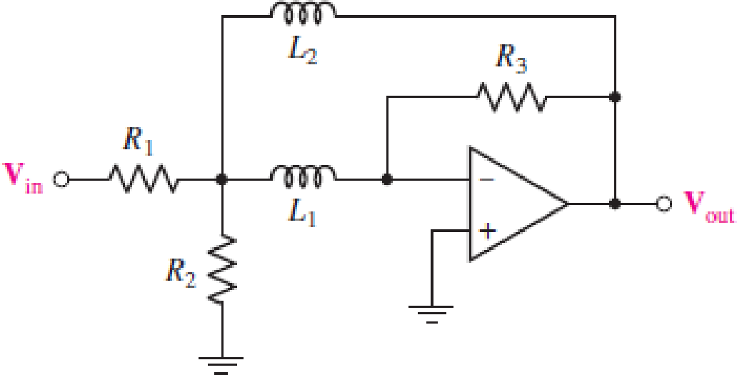
For the circuit in Fig. 15.57, (a) determine the transfer function H(s) = Vout/Vin in terms of circuit parameters R1, R2, R3, L1, and L2; (b) determine the magnitude and phase of the transfer function at ω = 0, 3 × 10³ rad/s, and as ω → ∞ for the case where circuit values are R1 = 2 kΩ, R2 = 2 kΩ, R3 = 20 kΩ, L1 = 2 H, and L2 = 2 H.
FIGURE 15.57
(a)
The transfer function
Answer to Problem 7E
The transfer function
Explanation of Solution
Given data:
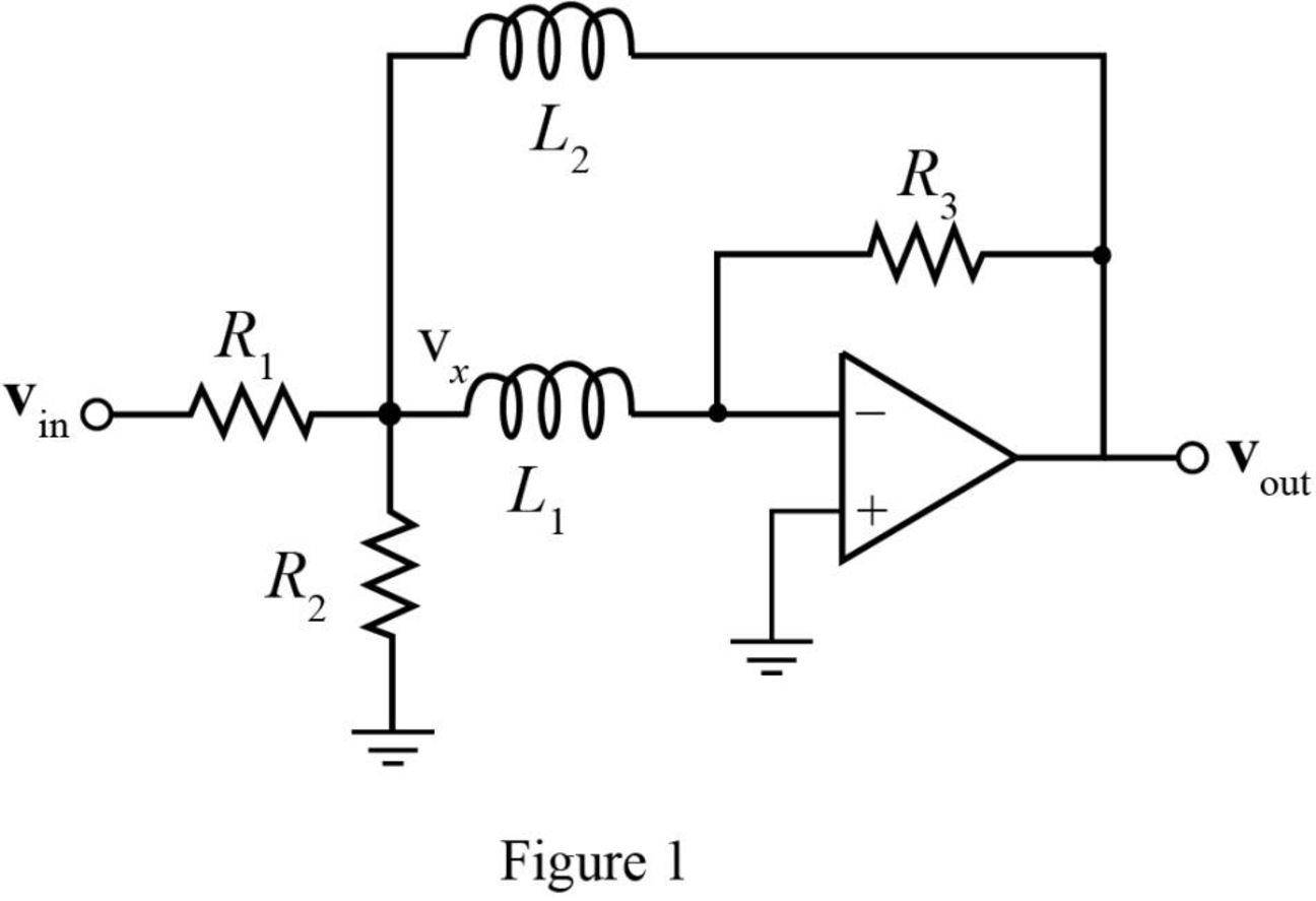
The required diagram is shown in Figure 1.
Calculation:
Assign the node intersecting the two resistors
The KCL equation at node
The KCL equation at node
Here,
Simplifying the equation (2) as,
The transfer function
Substitute
Substitute
Conclusion:
Therefore, the transfer function
(b)
The magnitude of transfer function
Answer to Problem 7E
The magnitude of transfer function
Explanation of Solution
Given data:
The resistance
The resistance
The resistance
The inductance
The inductance
The angular frequency
The angular frequency
The angular frequency
Calculation:
The conversion of
The conversion of
The conversion of
The magnitude of transfer function
The phase of transfer function
Substitute
Substitute
The magnitude of transfer function
The phase of transfer function
Substitute
Substitute
The magnitude of transfer function
The phase of transfer function
Substitute
Substitute
Conclusion:
Therefore, the magnitude of transfer function
Want to see more full solutions like this?
Chapter 15 Solutions
Engineering Circuit Analysis
Additional Engineering Textbook Solutions
Database Concepts (8th Edition)
Mechanics of Materials (10th Edition)
Starting Out with Programming Logic and Design (5th Edition) (What's New in Computer Science)
SURVEY OF OPERATING SYSTEMS
Elementary Surveying: An Introduction To Geomatics (15th Edition)
Java: An Introduction to Problem Solving and Programming (8th Edition)


- HW3: A 9.375-GHz uniform plane wave is propagating in polyethylene (&-2.26). If the amplitude of the electric field intensity is 500 V/m and the material is assumed to be lossless, find: (a) the phase constant; (b) thearrow_forwardHW1: The location of the sliding bar in Figure below is given by x = 5t + 2t³, and the separation of the two rails is 20 cm. Let B = 0.8x2a, T. Find the voltmeter reading at (a) t = 0.4 s; (b) x = 0.6 m.arrow_forwardFor the circuit shown in Fig. 2.18, he =1.1 K2, hfe =50. Find Avf, Rif and Rof. { Ans: -3.2; 1935; X2807. Ans:-3-2;193;728. Vcc Rs=10kQ RF = 40kQ Re=4KQ -ov Vsarrow_forward
- For the system shown in figure below, the per unit values of different quantities are E-1.2, V 1, X X2-0.4. Xa-0.2 Determine whether the system is stable for a sustained fault. The fault is cleared at 8-60°. Is the system stable? If so find the maximum rotor swing. Find the critical clearing angle. E25 G X'd 08 CB X2 F CB V28 Infinite busarrow_forward17 For the circuit shown in Fig. 2.20, the transistors are identical and have the following parameters: hfe = 50, hie 1.1K, hre = 0, and hoe = 0. Calculate Auf, Rif and Rof. 25 V {Ans #45.4; 112 KM; 129 150k 47k www www +11 www 10k 6 4.7k 50μF Rif R₂1000 w 4.7k 47k Vo Q2 33k 4.7k ww 50µF 5μF 4.7k 1 R₁ Rofarrow_forwardFor the circuit shown in Fig. 2.18, he =1.1 K2, hfe =50. Find Avf, Rif and Rof. { Ans: -3.2; 1935; X2807. Ans:-3-2;193;728. Vcc Rs=10kQ RF = 40kQ Re=4KQ -ov Vs Fig. 2.18 Circuit for Q5.arrow_forward
- The circuit of Fig. 2.16 is to have Af=-1mA/V, D=1+ BA = 50, a voltage gain of -4, Rs =1KQ, and hfe = 150. Find RL, Re, Rif and Rof.. Vcc www RL OV Ans: 4 kor; 98053150 KS;∞. { An Re Fig. 2.16 Circuit for Q3.arrow_forwardDuring the lab you will design and measure a differential amplifier, made with an opamp. inside generator R5 ww 500 V1 0.1Vpk 1kHz 0° R6 w 50Ω R1 ww 10ΚΩ VCC C1 balanced wire R3 w 15.0V signal+ 100nF U1A TL082CP ground 2 signal- R4 w C2 Question5: Calculate R3 and R4 for a 20dB. 100nF VEE -15.0V R2 ww 10ΚΩarrow_forwardnot use ai pleasearrow_forward
- 3. Consider the system described by the transfer function Gp(s) polynomial controller to satisfy the below specifications: 1) The settling time is t = 1 second, 2) 0.1% peak overshoot, 3) and zero steady-state error for a ramp input. The sampling period is T = 0.01 second. 1 = Design a discrete-time s(s+5)*arrow_forwardProblem 2 Does there exist a value a that makes the two systems S₁ and S₂ equal? If so, what is this value ? If not, explain why. S₁ x[n] x[n] D D -2 → host 回洄 S with h[m] " 999. усиз -1012345 harrow_forwardplease not use any aiarrow_forward
 Introductory Circuit Analysis (13th Edition)Electrical EngineeringISBN:9780133923605Author:Robert L. BoylestadPublisher:PEARSON
 Delmar's Standard Textbook Of ElectricityElectrical EngineeringISBN:9781337900348Author:Stephen L. HermanPublisher:Cengage Learning
 Programmable Logic ControllersElectrical EngineeringISBN:9780073373843Author:Frank D. PetruzellaPublisher:McGraw-Hill Education
 Fundamentals of Electric CircuitsElectrical EngineeringISBN:9780078028229Author:Charles K Alexander, Matthew SadikuPublisher:McGraw-Hill Education
 Electric Circuits. (11th Edition)Electrical EngineeringISBN:9780134746968Author:James W. Nilsson, Susan RiedelPublisher:PEARSON
 Engineering ElectromagneticsElectrical EngineeringISBN:9780078028151Author:Hayt, William H. (william Hart), Jr, BUCK, John A.Publisher:Mcgraw-hill Education,