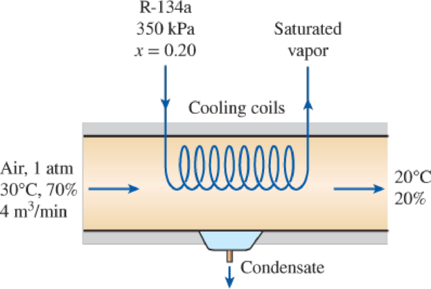
Atmospheric air enters an air-conditioning system at 30°C and 70 percent relative humidity with a volume flow rate of 4 m3/min and is cooled to 20°C and 20 percent relative humidity at a pressure of 1 atm. The system uses refrigerant-134a as the cooling fluid that enters the cooling section at 350 kPa with a quality of 20 percent and leaves as a saturated vapor. Show the process on the psychrometric chart. What is the heat transfer from the air to the cooling coils, in kW? If any water is condensed from the air, how much water will be condensed from the atmospheric air per min? Determine the mass flow rate of the refrigerant, in kg/min.

FIGURE P14–132
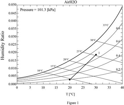
Show the process on the psychrometric chart; find the heat transfer from the air to the cooling coils, how much water will be condensed from the atmospheric air per min and the mass flow rate of the refrigerant.
Answer to Problem 132RP
The process on the psychrometric chart is shown below in Figure (1), the heat transfer from the air to the cooling coils is
Explanation of Solution
As the process is a steady flow and thus the mass flow rate of dry air remains constant during the entire process.
Here, the mass flow rate of air at inlet is
Express the mass flow rate of dry air.
Here, volume flow rate at inlet is
Express the mass flow rate of vapor at inlet.
Here, specific humidity at state 1 is
Express the mass flow rate of vapor at exit.
Here, specific humidity at state 2 is
Express the rate of condensation of water.
Express the enthalpy of condensate water.
Here, enthalpy of saturation liquid at temperature of
Express the rate required heat transfer rate from the atmospheric air to the evaporator fluid from an energy balance on the control volume.
Here, enthalpy at state 1 and 2 is
Express enthalpy of refrigerant at inlet.
Here, quality of refrigerant at inlet is
Express enthalpy of refrigerant at exit.
Here, quality of refrigerant at exit is
Express the mass flow rate of the refrigerant.
Here, enthalpy of refrigerant at inlet and exit is
Conclusion:
Show the psychrometric diagram as in Figure (1).

Hence, the psychrometric diagram is shown in Figure (1).
Refer Figure A-31, “psychometric chart at
Refer Figure A-31, “psychometric chart at
Substitute
Substitute
Substitute
Substitute
Hence, the amount of water condensed from the atmospheric air per min is
Refer Table A-4, “saturated water-temperature table”, and write the enthalpy of condensate water at temperature of
Here, enthalpy of saturation liquid is
Substitute
Substitute
Hence, the heat transfer from the air to the cooling coils is
Refer Table A-12, saturated refrigerant-134a-presure table”, and write enthalpy of saturation liquid at pressure of
Write the formula of interpolation method of two variables.
Here, the variables denote by x and y pressure and enthalpy of saturation liquid respectively.
Show the enthalpy of saturation liquid corresponding to pressure as in Table (1).
|
Pressure |
Enthalpy of saturation liquid |
| 320 | 55.14 |
| 350 | |
| 360 | 59.70 |
Substitute
Thus, the enthalpy of saturation liquid at pressure of
Refer Table A-12, saturated refrigerant-134a-presure table”, and write enthalpy of saturation vapor at pressure of
Show the enthalpy of saturation vapor corresponding to pressure as in Table (2).
|
Pressure |
Enthalpy of saturation liquid |
| 320 | 251.93 |
| 350 | |
| 360 | 253.86 |
Use excels and tabulates the values form Table (2) in Equation (X) to get,
Substitute
Substitute
Substitute
Hence, the mass flow rate of the refrigerant is
Want to see more full solutions like this?
Chapter 14 Solutions
THERMODYNAMICS (LL)-W/ACCESS >CUSTOM<
- A ship of 10 000 tonne displacement has a waterplanearea of 1300 m2. The ship loads in water of 1.010 t/m3 andmoves into water of 1.026 t/m3. Find the change in meandraughtarrow_forwardA ship of 7000 tonne displacement has a waterplane areaof 1500 m2. In passing from sea water into river water of1005 kg/m3 there is an increase in draught of 10 cm. Find the Idensity of the sea water.arrow_forwardA ship has 300 tonne of cargo in the hold, 24 m forward ofmidships. The displacement of the vessel is 6000 tonne and its centre of gravity is 1.2 m forward of midships.Find the new position of the centre of gravity if this cargo ismoved to an after hold, 40 m from midshipsarrow_forward
- Sketch and describe how ships are supported in dry dock. When and where does the greatest amount of stresses occur?arrow_forwardSketch and desribe a balanced rudder and how it is suspendedarrow_forwardA ship 140 m long and 18 m beam floats at a draught of9 m. The immersed cross-sectionai areas at equai intervais are 5,60, 116, 145, 152, 153, 153, 151, 142, 85 and 0 m2 respectively.Calculate:(a) displacement(b) block coefficient(c) midship section area coefficient(d) prismatic coefficient.arrow_forward
- A steamer has waterplane area 1680m2 recorded in water with relative denisty 1.013. Displacement = 1200 t, calculate difference in draught in salwater reltive denisity 1.025.arrow_forwardrelative velocity 11.72 m/s is correct, need help finding the angle pleasearrow_forwardDetermine the distance between the two automobiles 2 s after A has passed through the intersection.arrow_forward
- A box barge 65 m long and 12 m wide floats at a draught of5.5 m in sea water. Calculate:(a) the displacement of the barge,(b) its draught in fresh waterarrow_forwardwhat is the angle of the velocity of block B? velocity is 7.46 in/s Determine the acceleration and angle of block B. (Round the acceleration value to three decimal places.)arrow_forwardDetermine the relative velocity of B with respect to A.arrow_forward
 Elements Of ElectromagneticsMechanical EngineeringISBN:9780190698614Author:Sadiku, Matthew N. O.Publisher:Oxford University Press
 Mechanics of Materials (10th Edition)Mechanical EngineeringISBN:9780134319650Author:Russell C. HibbelerPublisher:PEARSON
 Thermodynamics: An Engineering ApproachMechanical EngineeringISBN:9781259822674Author:Yunus A. Cengel Dr., Michael A. BolesPublisher:McGraw-Hill Education
 Control Systems EngineeringMechanical EngineeringISBN:9781118170519Author:Norman S. NisePublisher:WILEY
 Mechanics of Materials (MindTap Course List)Mechanical EngineeringISBN:9781337093347Author:Barry J. Goodno, James M. GerePublisher:Cengage Learning
 Engineering Mechanics: StaticsMechanical EngineeringISBN:9781118807330Author:James L. Meriam, L. G. Kraige, J. N. BoltonPublisher:WILEY


