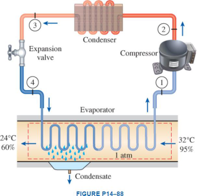
Atmospheric air at 1 atm, 32°C, and 95 percent relative humidity is cooled to 24°C and 60 percent relative humidity. A simple ideal vapor-compression refrigeration system using refrigerant-134a as the working fluid is used to provide the cooling required. It operates its evaporator at 4°C and its condenser at a saturation temperature of 39.4°C. The condenser rejects its heat to the atmospheric air. Calculate the exergy destruction, in kJ, in the total system per 1000 m3 of dry air processed.

The exergy destruction in the total system per
Answer to Problem 88P
The exergy destruction in the total system per
Explanation of Solution
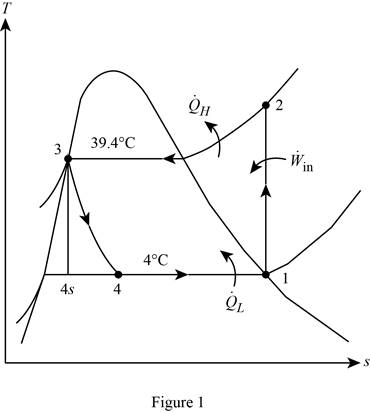
Show the T-s diagram for the simple ideal vapour-compression refrigeration system.

Express the mass of air.
Here, volume at state 1 is
Express the water mass balance and energy balance equations to the combined cooling and dehumidification section.
For water mass balance:
For energy balance:
Write the energy balance equation using steady-flow equation.
Here, the rate of total energy entering the system is
Substitute
Here, the specific enthalpy at the state 1 and 2 are
Write the formula for mass flow rate of refrigerant-134a.
Write the formula for amount of heat rejected from the condenser.
Calculate the exergy destruction in the components of the refrigeration cycle.
For the process 1-2,
Here, the process 1-2 is an isentropic.
For the process 2-3,
For the process 3-4,
Write the entropy change of water vapour in the air stream.
Write the entropy of water leaving the cooling section.
Determine the partial pressure of water vapour at state 1 for air steam.
Determine the partial pressure of dry air at state 1 for air steam.
Here, the pressure at the state 1 is
Determine the partial pressure of water vapour at state 2 for air steam.
Determine the partial pressure of dry air at state 2 for air steam.
Here, the pressure at the state 2 is
Write the formula for entropy change of dry air.
Write the formula for entropy change R-134a in the evaporator.
Write the formula for an entropy balance on the evaporator.
Write the formula for an exergy destruction in the evaporator.
Write the formula for the total exergy destruction.
Conclusion:
Refer Figure A-31, “psychometric chart at
Refer Table A-4, “saturated water-temperature table”, and write the specific enthalpy of condensate water at temperature of
Here, entropy of saturation liquid at temperature of
Write the formula of interpolation method of two variables.
Here, the variables denote by x and y is temperature and specific enthalpy of condensate water at state 2 respectively.
Show the specific enthalpy of condensate water at corresponding to temperature as in Table (1).
|
Temperature |
Specific enthalpy of condensate water |
| 25 | 104.83 |
| 28 | |
| 30 | 125.74 |
Substitute
Substitute
Substitute
Substitute 1105 kg for
Substitute 1105 kg for
From the Table A-11 “Saturated Refrigerant-134a-Pressure Table”, obtain the value of the specific enthalpy and entropy at state 1 of
Refer Table A-13 “Saturated Refrigerant-134a-Pressure Table”, and write the specific enthalpy at state 2 in 1 MPa of pressure and entropy of
From the Table A-12 “Saturated Refrigerant-134a-Pressure Table”, obtain the value of the specific enthalpy and entropy at state 3 of
Here, the specific enthalpy at the state 4 and 3 are equal in the throttling.
Calculate the value of
From the Table A-11 “Saturated Refrigerant-134a-Pressure Table”, obtain the value of the specific enthalpy and entropy of saturated liquid and change upon vaporization at state 4 of
Substitute
Calculate the value of specific entropy of the state 4.
Substitute
Substitute
Substitute
Substitute
Substitute
Refer Table A-4 “Saturated water-temperature Table”, and write the specific entropy at state 1 at
Refer Table A-4 “Saturated water-temperature Table”, and write the specific entropy at state 1 at
Substitute
Substitute
Substitute
Substitute
Substitute
Substitute
Substitute
Substitute
Substitute
Substitute
Substitute 0 for
Thus, the exergy destruction in the total system per
Want to see more full solutions like this?
Chapter 14 Solutions
THERMODYNAMICS (LL)-W/ACCESS >CUSTOM<
- An Inclining experiment done on a ship thats 6500 t, a mass of 30t was moved 6.0 m transvesly causing a 30 cm deflection in a 6m pendulum, calculate the transverse meta centre height.arrow_forwarda ship 150 m long and 20.5 m beam floats at a draught of8 m and displaces 19 500 tonne. The TPC is 26.5 and midshipsection area coefficient 0.94. Calculate the block, prismatic andwaterplane area coefficients.arrow_forwardA vessel loads 680 t fuel between forward and aft deep tanks. centre of gravity of forward tank is 24m forward of ships COG. centre to centre between tanks is 42 m. how much in each tank to keep trim the samearrow_forward
- Beam of a vessel is 11% its length. Cw =0.72. When floating in SW of relative denisity 1.03, TPC is 0.35t greater than in freshwater. Find the length of the shiparrow_forwardAn inclining experiment was carried out on a ship of 4000tonne displacement, when masses of 6 tonne were moved transverselythrough 13.5 m. The deflections of a 7.5 m pendulurnwere 81, 78, 85, 83, 79, 82, 84 and 80 mm respectively.Caiculate the metacentric height.arrow_forwardA ship of 10 000 tonne displacement has a waterplanearea of 1300 m2. The ship loads in water of 1.010 t/m3 andmoves into water of 1.026 t/m3. Find the change in meandraughtarrow_forward
- A ship of 7000 tonne displacement has a waterplane areaof 1500 m2. In passing from sea water into river water of1005 kg/m3 there is an increase in draught of 10 cm. Find the Idensity of the sea water.arrow_forwardA ship has 300 tonne of cargo in the hold, 24 m forward ofmidships. The displacement of the vessel is 6000 tonne and its centre of gravity is 1.2 m forward of midships.Find the new position of the centre of gravity if this cargo ismoved to an after hold, 40 m from midshipsarrow_forwardSketch and describe how ships are supported in dry dock. When and where does the greatest amount of stresses occur?arrow_forward
- Sketch and desribe a balanced rudder and how it is suspendedarrow_forwardA ship 140 m long and 18 m beam floats at a draught of9 m. The immersed cross-sectionai areas at equai intervais are 5,60, 116, 145, 152, 153, 153, 151, 142, 85 and 0 m2 respectively.Calculate:(a) displacement(b) block coefficient(c) midship section area coefficient(d) prismatic coefficient.arrow_forwardA steamer has waterplane area 1680m2 recorded in water with relative denisty 1.013. Displacement = 1200 t, calculate difference in draught in salwater reltive denisity 1.025.arrow_forward
 Refrigeration and Air Conditioning Technology (Mi...Mechanical EngineeringISBN:9781305578296Author:John Tomczyk, Eugene Silberstein, Bill Whitman, Bill JohnsonPublisher:Cengage Learning
