
ENGINEERING CIRCUIT...(LL)>CUSTOM PKG.<
9th Edition
ISBN: 9781260540666
Author: Hayt
Publisher: MCG CUSTOM
expand_more
expand_more
format_list_bulleted
Concept explainers
Videos
Textbook Question
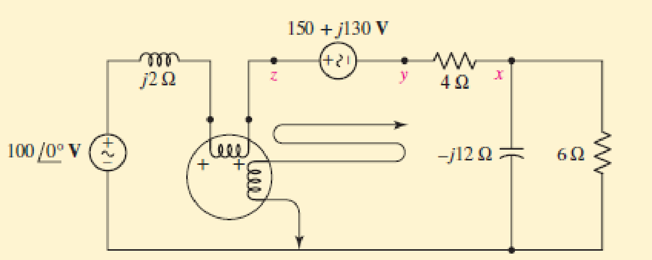
Chapter 12.5, Problem 9P
Determine the wattmeter reading in Fig. 12.24, state whether or not the potential coil had to be reversed in order to obtain an upscale reading, and identify the device or devices absorbing or generating this power. The (+) terminal of the wattmeter is connected to (a) x; (b) y; (c) z.
Expert Solution & Answer
Want to see the full answer?
Check out a sample textbook solution
Students have asked these similar questions
not use ai
For the Fig.
name, derive and determine all gains, frequency and draw the output
waveform. Choose Q-15, and Q=6. Choose C₁-20 µF, C₂-5 µF, L=25mH.
R₂
12
HH
1. (30pts) The input to a system is a DC component, a message, m(t), and a carrier,
c(t). The output of the system is the square of the sum of the inputs. Determine
if it is possible to retrieve DSB-SC modulated waveform. Show your work.
Chapter 12 Solutions
ENGINEERING CIRCUIT...(LL)>CUSTOM PKG.<
Ch. 12.1 - Let and . Find (a) Vad; (b) Vbc; (c) Vcd.Ch. 12.2 - Prob. 2PCh. 12.2 - Modify Fig. 12.9 by adding a 1.5 resistance to...Ch. 12.3 - A balanced three-phase three-wire system has a...Ch. 12.3 - A balanced three-phase three-wire system has a...Ch. 12.3 - Three balanced Y-connected loads are installed on...Ch. 12.4 - Each phase of a balanced three-phase -connected...Ch. 12.4 - Prob. 8PCh. 12.5 - Determine the wattmeter reading in Fig. 12.24,...Ch. 12.5 - Prob. 10P
Ch. 12 - Prob. 1ECh. 12 - Prob. 2ECh. 12 - Prob. 3ECh. 12 - Describe what is meant by a polyphase source,...Ch. 12 - Prob. 5ECh. 12 - Prob. 6ECh. 12 - Prob. 7ECh. 12 - Prob. 8ECh. 12 - Prob. 9ECh. 12 - Prob. 10ECh. 12 - The single-phase three-wire system of Fig. 12.31...Ch. 12 - Prob. 12ECh. 12 - Referring to the balanced load represented in Fig....Ch. 12 - Prob. 14ECh. 12 - Prob. 15ECh. 12 - Consider a simple positive phase sequence,...Ch. 12 - Assume the system shown in Fig. 12.34 is balanced,...Ch. 12 - Repeat Exercise 17 with Rw = 10 , and verify your...Ch. 12 - Prob. 19ECh. 12 - Prob. 20ECh. 12 - Prob. 21ECh. 12 - Prob. 22ECh. 12 - A three-phase system is constructed from a...Ch. 12 - Prob. 24ECh. 12 - Each load in the circuit of Fig. 12.34 is composed...Ch. 12 - Prob. 26ECh. 12 - Prob. 27ECh. 12 - A three-phase load is to be powered by a...Ch. 12 - For the two situations described in Exercise 28,...Ch. 12 - Prob. 30ECh. 12 - Prob. 31ECh. 12 - Prob. 32ECh. 12 - Repeat Exercise 32 if Rw = 1 . Verify your...Ch. 12 - Prob. 34ECh. 12 - Prob. 35ECh. 12 - Prob. 36ECh. 12 - A wattmeter is connected into the circuit of Fig....Ch. 12 - Find the reading of the wattmeter connected in the...Ch. 12 - (a) Find both wattmeter readings in Fig. 12.39 if...Ch. 12 - Circuit values for Fig. 12.40 are , , , , . Find...Ch. 12 - Prob. 41ECh. 12 - Prob. 42ECh. 12 - (a) Is the load represented in Fig. 12.41...Ch. 12 - Prob. 44E
Knowledge Booster


Learn more about
Need a deep-dive on the concept behind this application? Look no further. Learn more about this topic, electrical-engineering and related others by exploring similar questions and additional content below.Similar questions
- 2) (20pts) m(t) and an unmodulated carrier, c(t), are given below m(t) = 2.2 cos(2л400t) – 7 cos(2л700t) +5 cos(2500) volts c(t) = 6 cos(2л2000) volts Sketch the amplitude spectrum for a Double Sideband Suppressed Carrier modulated waveform. You must carefully label all axes and provide each frequency component value (the x-value); each amplitude in Volts/Hz (the y-value). Include both negative and positive frequencies.arrow_forwardnot use ai pleasearrow_forwardFor the circuit shown, find the voltage vo using superposition. Let Vs1-11, V2=27 V, 1-4, R₁-8 02, R2=5 Q2, R3-17 02, R4-2002 and R5-14 02. In particular show your values for: V01, Vo due to Is only: V01- V02, Vo due to V51 only: Voz V03, Vo due to V52 only: V03= Then Vo Vo VSI +1 RI ww ww V. IS V. V. V. R3 R5 ww www + Vo R2 www R4 V$2 The relative tolerance for this problem is 10 %.arrow_forward
- For the circuit shown, let V-28, I-5, R₁=50, R₂-802, R3-2002, R4-17 2 and R5-11 Q, determine the maximum power dissipated by the load resistor R₁ as follows: ■ Find VTH seen by the load resistor R₁, VTh= (V) (50%) ⚫ {Hint: You can use superposition or any other method. } Find RTH seen by the load resistor RL, RT= (Q) (25%) ■ maximum power dissipated by the load resistor R₁: (W) (25%) Is R5 R 1 ww w R3 Vs ± R2 w R4 w RL + Vo The relative tolerance for this problem is 10 %.arrow_forward3) (40 pts) An FM modulated carrier is modulated by the following signal: m(t) = 4 cos(2л * (1000) *t) volts The modulator uses a frequency deviation of 3 KHz. The unmodulated carrier is: * c(t) = 5 cos(2π (100,000) *t) volts a) (10pts) What would be a good estimate of the bandwidth of modulated signal?arrow_forwardOnly expert should attemptarrow_forward
- For the circuit shown, let Vs1-20, Vs2= 8 V, R₁=6 02, R₂-402, R3-8 Q, and R4-5 0, find the voltage Vx and Vo using superposition and voltage division as follows: [Note: You are given to 2 attempts.] 1. Determine Vx (choose the closet value): Vx = V. ○ 10.963 ○ 8.77 2.696 3.852 4.933 O 4.622 O 1.541 2. Use Vx to find Vo (choose the closet value): Vo V. 0.428 1.797 ○ 3.081 none of the listed values 1.284 0.285 ○ 2.568 = VS1 +1 ww R1 Vx R2 ww R3 ww R4 ww The relative tolerance for this problem is 10%. + Vo - +1 V$2arrow_forwardFor the circuit shown below, find the voltage V using superposition. Let V-28 V, I-4, R₁=5 Q, R₂-20 0, R3-15 Q and R4-10 Q2. In particular calculate: V due to V₂ only- V due to l₂ only- V due to Vs and I V S (+ 1) V. V R3 V R4 IS RI The relative tolerance for this problem is 10%. + R₂ warrow_forwardplease solve, thank youarrow_forward
- For the circuit shown, let V-24, I-5, R₁=17 Q, R₂=1102, R3-14, R4-5 0 and R5-20 then find the Thevenin equivalent circuits for the following 2 cases: 1. seen from terminal a-b: " RTH VTH 2. seen from terminal b-c: " RTH VTH = Vs +1 R2 www R4 R1 R5 R3 ww Is Carrow_forwardFundamentals of Energy Systems HW5 Q3arrow_forwardFundamentals of Energy Systems HW5 Q8arrow_forward
arrow_back_ios
SEE MORE QUESTIONS
arrow_forward_ios
Recommended textbooks for you
 Introductory Circuit Analysis (13th Edition)Electrical EngineeringISBN:9780133923605Author:Robert L. BoylestadPublisher:PEARSON
 Delmar's Standard Textbook Of ElectricityElectrical EngineeringISBN:9781337900348Author:Stephen L. HermanPublisher:Cengage Learning
 Programmable Logic ControllersElectrical EngineeringISBN:9780073373843Author:Frank D. PetruzellaPublisher:McGraw-Hill Education
 Fundamentals of Electric CircuitsElectrical EngineeringISBN:9780078028229Author:Charles K Alexander, Matthew SadikuPublisher:McGraw-Hill Education
 Electric Circuits. (11th Edition)Electrical EngineeringISBN:9780134746968Author:James W. Nilsson, Susan RiedelPublisher:PEARSON
 Engineering ElectromagneticsElectrical EngineeringISBN:9780078028151Author:Hayt, William H. (william Hart), Jr, BUCK, John A.Publisher:Mcgraw-hill Education,
Introductory Circuit Analysis (13th Edition)
Electrical Engineering
ISBN:9780133923605
Author:Robert L. Boylestad
Publisher:PEARSON
Delmar's Standard Textbook Of Electricity
Electrical Engineering
ISBN:9781337900348
Author:Stephen L. Herman
Publisher:Cengage Learning
Programmable Logic Controllers
Electrical Engineering
ISBN:9780073373843
Author:Frank D. Petruzella
Publisher:McGraw-Hill Education
Fundamentals of Electric Circuits
Electrical Engineering
ISBN:9780078028229
Author:Charles K Alexander, Matthew Sadiku
Publisher:McGraw-Hill Education
Electric Circuits. (11th Edition)
Electrical Engineering
ISBN:9780134746968
Author:James W. Nilsson, Susan Riedel
Publisher:PEARSON
Engineering Electromagnetics
Electrical Engineering
ISBN:9780078028151
Author:Hayt, William H. (william Hart), Jr, BUCK, John A.
Publisher:Mcgraw-hill Education,
How do Electric Transmission Lines Work?; Author: Practical Engineering;https://www.youtube.com/watch?v=qjY31x0m3d8;License: Standard Youtube License