
Concept explainers
Videos
Repeat Exercise 17 with Rw = 10 Ω, and verify your answers with an appropriate set of simulations if the operating frequency is 60 Hz.
Assume the system shown in Fig. 12.34 is balanced, Rw = 0, Van = 208∠0° V, and a positive phase sequence applies. Calculate all phase and line currents, and all phase and line voltages, if Zp is equal to (a) 1 kΩ; (b) 100 + j48 Ω; (c) 100 − j48 Ω.
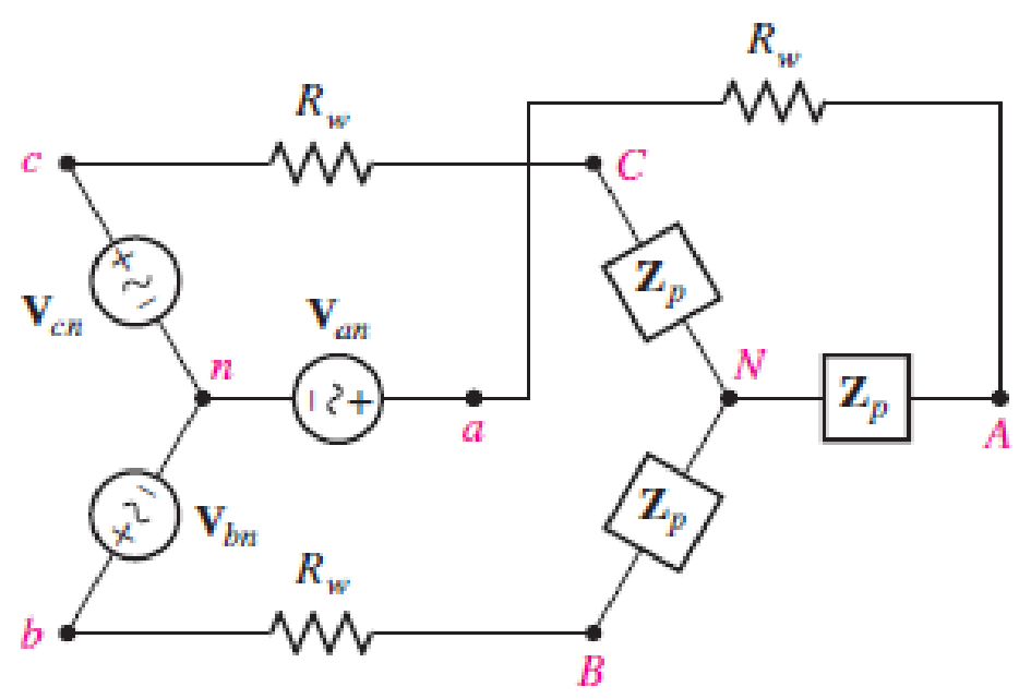
■ FIGURE 12.34
(a)
Find the line and phase currents, line and phase voltages at the load when the load impedance
Answer to Problem 18E
The line and phase currents are
Explanation of Solution
Given data:
The line resistance
The load impedance
The source phase voltage is
The simulation operation frequency is
LTspice Simulation:
Draw the given circuit diagram as shown in Figure 1, where 1, 2, and 3 are placed for node representations using Label Net.
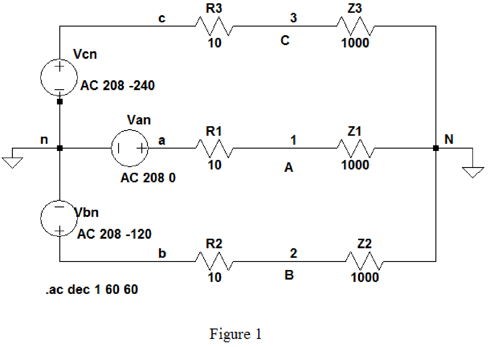
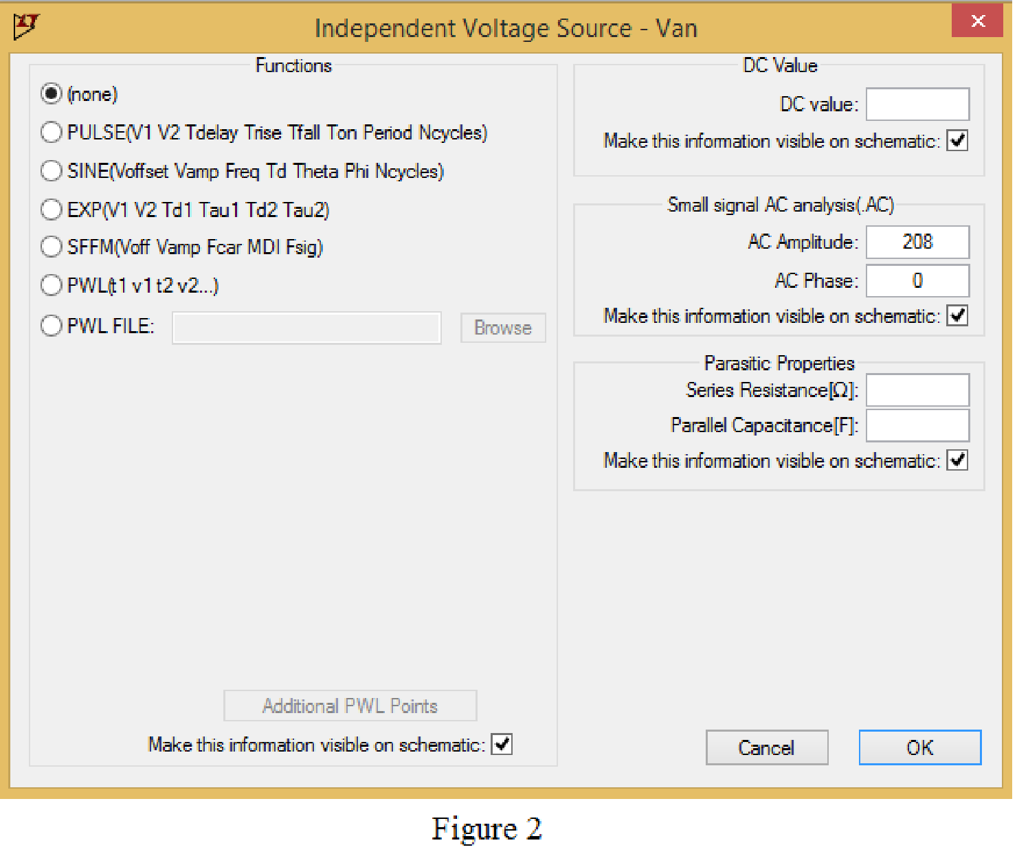
Set the values of voltages Van, Vbn and Vcn by right clicking on the voltage component, select none in “Functions” and enter the Small signal AC analysis parameters: AC amplitude as 208 and AC phase as 0 for V1, and enter other two voltage values accordingly positive phase sequence as shown in Figure 2 for V1.
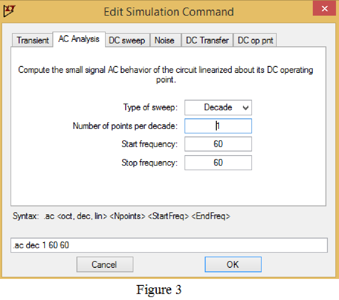
Now save the circuit, and open the “Edit Simulation command” choose AC analysis and select the sweep type as Decade, Number of points per decade 1, Start frequency and Stop frequency as 60 Hz shown in Figure 3.
Now, run the simulation for the designed circuit. The output for the AC analysis will displays as shown in Figure 4.
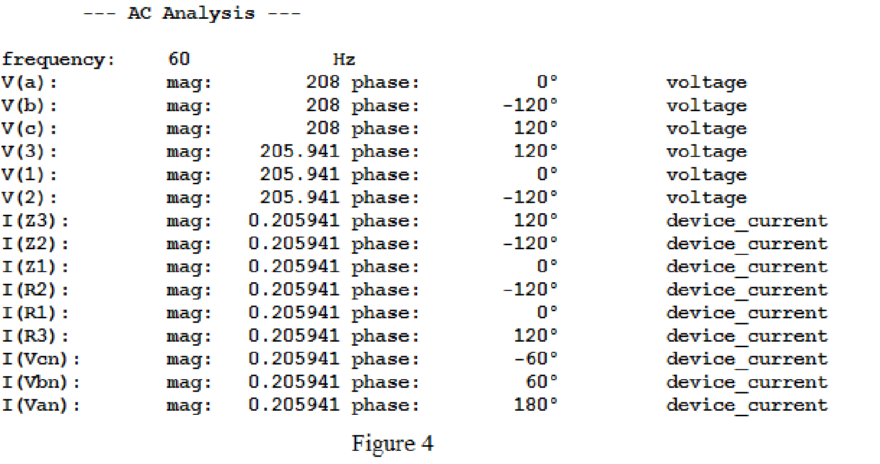
For the wye-wye connection, phase currents and line currents are equal and they are equals to
Then,
In above simulation results, the phase voltages at the load
Then, the phase voltages at the load are,
The magnitude of the phase voltages is
Write the formula to find the line voltage
Substitute
Write the formula to find the line voltage
Substitute
Write the formula to find the line voltage
Substitute
Conclusion:
Thus, the line and phase currents are
(b)
Find the line and phase currents, line and phase voltages at the load when the load impedance
Answer to Problem 18E
The line and phase currents are
The phase voltages are
Explanation of Solution
Given data:
Refer to part (a).
LTspice Simulation:
The load impedance is given as,
Where load resistance is
Write the formula to find the inductive reactance as follows.
Substitute
Draw the given circuit diagram as shown in Figure 5 for the load impedance
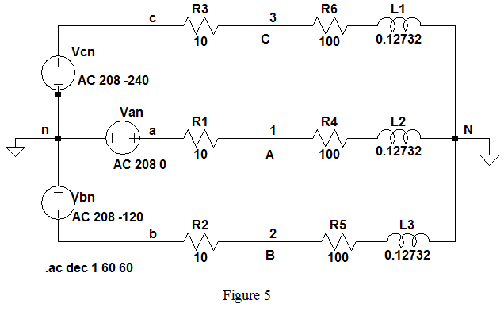
Keep the same simulation settings as given in Part(a) and run the simulation, then the output for the AC analysis will displays as shown in Figure 6.
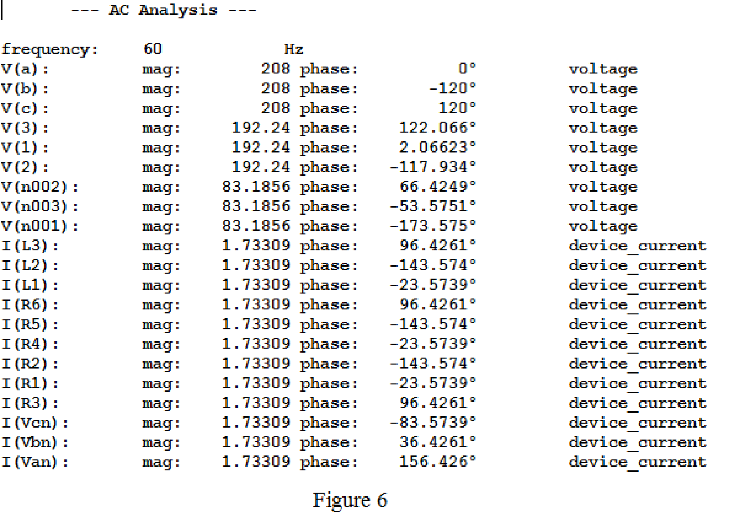
From above simulation results I(R1) or I(R4) or I(L1) is equals to
Then,
The phase voltages at the load
Then, the phase voltages at the load are,
The magnitude of the phase voltages is
Write the formula to find the line voltage
Substitute
Write the formula to find the line voltage
Substitute
Write the formula to find the line voltage
Substitute
Conclusion:
Thus, the line and phase currents are
The phase voltages are
(c)
Find the line and phase currents, line and phase voltages at the load when the load impedance
Answer to Problem 18E
The line and phase currents are
The phase voltages are
Explanation of Solution
Given data:
Refer to part (a).
LTspice Simulation:
The load impedance is given as,
Where load resistance is
Write the formula to find the inductive reactance as follows.
Substitute
Draw the given circuit diagram as shown in Figure 5 for the load impedance
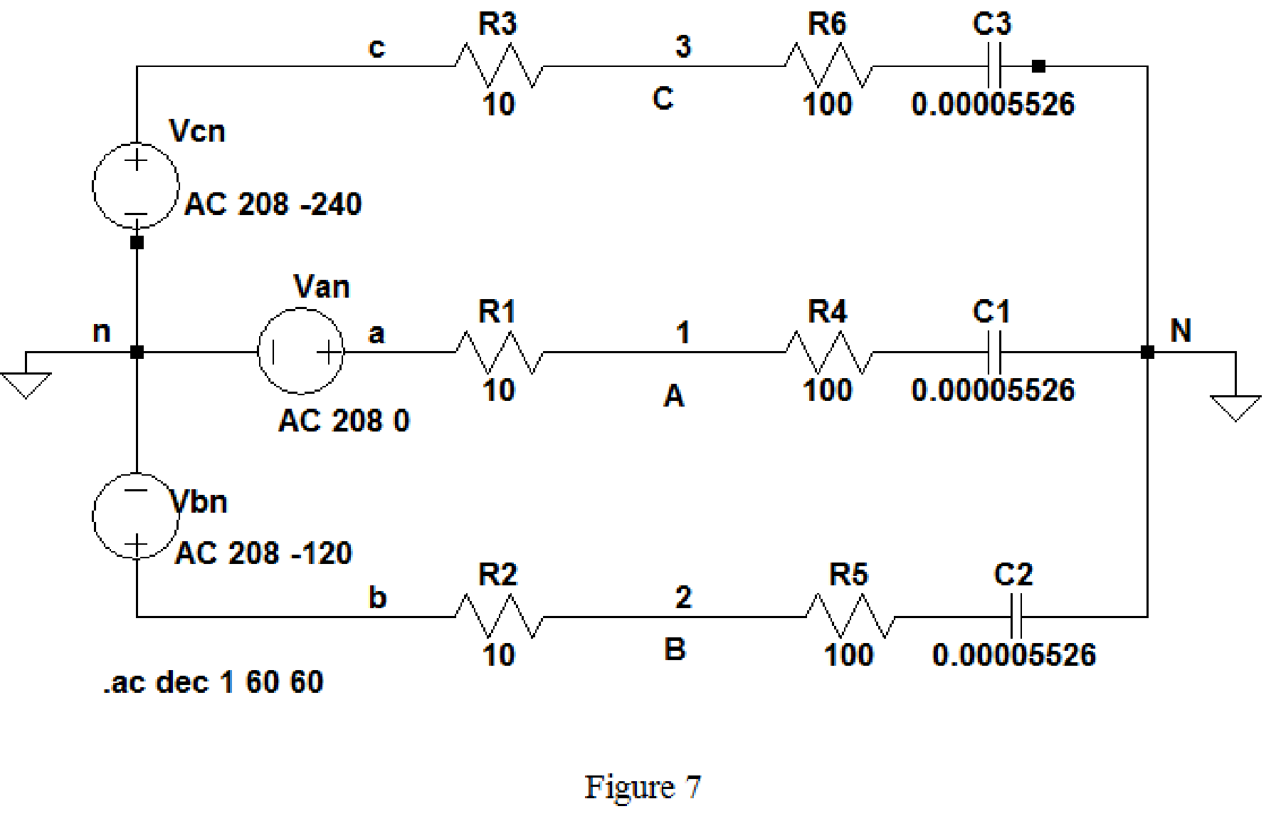
Keep the same simulation settings as given in part(a) and run the simulation, then the output for the AC analysis will displays as shown in Figure 8.
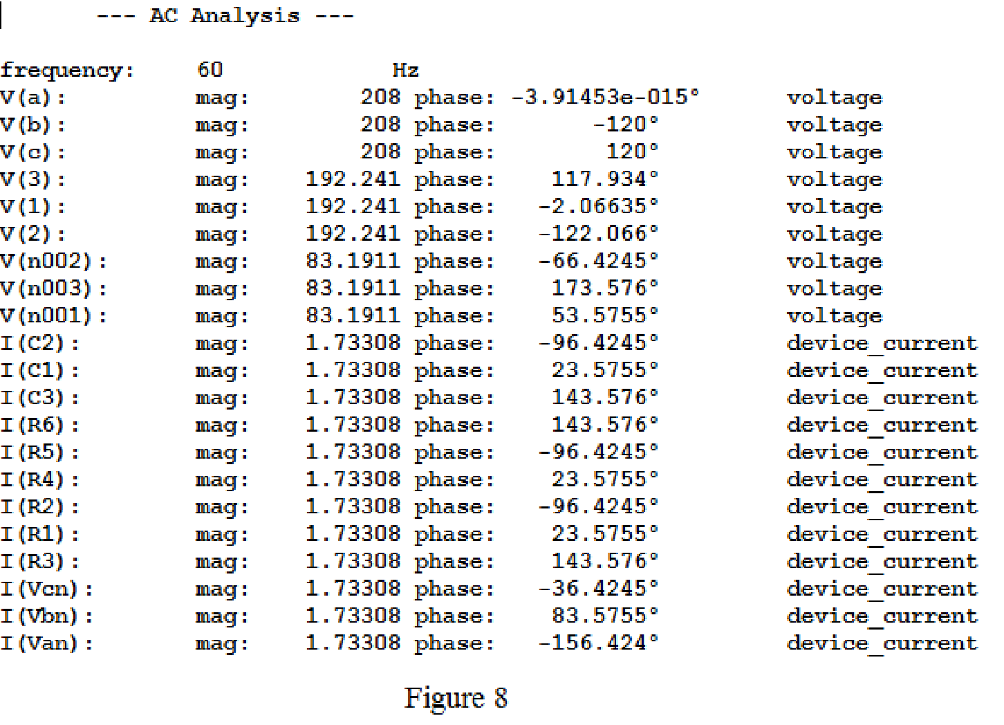
From above simulation results, since the phase currents and line currents are equal, I(R1) or I(R4) or I(C1) is equals to
Then,
The phase voltages at the load
Then, the phase voltages at the load are,
Use the same formula given in equation (1) to find the line voltage
Use the same formula given in equation (2) to find the line voltage
Use the same formula given in equation (3) to find the line voltage
Conclusion:
Thus, the line and phase currents are
The phase voltages are
Want to see more full solutions like this?
Chapter 12 Solutions
ENGINEERING CIRCUIT...(LL)>CUSTOM PKG.<


- Solve it in a different way than the previous solution that I searched forarrow_forwardA lossless uncharged transmission line of length L = 0.45 cm has a characteristic impedance of 60 ohms. It is driven by an ideal voltage generator producing a pulse of amplitude 10V and width 2 nS. If the transmission line is connected to a load of 200 ohms, sketch the voltage at the load as a function of time for the interval 0 < t < 20 nS. You may assume that the propagation velocity of the transmission is c/2. Answered now answer number 2. Repeat Q.1 but now assume the width of the pulse produced by the generator is 4 nS. Sketch the voltage at the load as a function of time for 0 < t < 20 nS.arrow_forwardSolve this experiment with an accurate solution, please. Thank you.arrow_forward
- A lossless uncharged transmission line of characteristic impedance Zo = 600 and length T = 1us is connected to a 180 load. If this transmission line is connected at t = 0 to a 90 V dc source with an internal resistance of 900, from a bounce diagram of this system sketch (a) the voltage at z=0, z=L, and z = L/2 for up to 7.25μs and (b) calculate the load voltage after an infinite amount of time.arrow_forwardA lossless uncharged transmission line of length L = 0.45 cm has a characteristic impedance of 60 ohms. It is driven by an ideal voltage generator producing a pulse of amplitude 10V and width 2 nS. If the transmission line is connected to a load of 200 ohms, sketch the voltage at the load as a function of time for the interval 0 < t < 20 nS. You may assume that the propagation velocity of the transmission is c/2.arrow_forwardThe VSWR (Voltage Standing Wave Ratio) is measured to be 2 on a transmission line. Find two values of the reflection coefficient with one corresponding to Z > Zo and the other to Zarrow_forwardA dc voltage of unknown value Vand internal resistance Reis connected through a switch to a lossless transmission line of Zo = 1000. If the first 5 μS of the voltages at z = 0 and z = L are observed to be as shown below, calculate Vo, RG, the load resistanceR,, and the transit time T. 100 + [V]:-0. V 90 [V]:-V 100 75 I, Տ 1,μs 2 4 6 0 2 4 6arrow_forwardA lossless open circuited transmission line behaves as an equivalent capacitance of Ceq = Tan (BL) Show for BL << 1 that Ceq = C'L where L is the length of the transmission line and wZo C' is the lumped parameter capacitance per unit length of the transmission line. Hint: For x small, Tan(x) = x.arrow_forward= A generator with VG 300V and R = 50 is connected to a load R = 750 through a 50 lossless transmission line of length L = 0.15 m. (a) Compute Zin, the input impedance of the line at the generator end. (b) Compute and V. (c) Compute the time-average power Pin delivered to the line. (d) Compute VL, IL, and the time-average power delivered to the load, PL (e) How does Pin compare to PL? Explain.arrow_forwardFor the regulated power supply circuit, assume regular diodes with 0.7V forward drop. Use a 15V (peak), 60Hz sine wave at the transformer secondary and assume a maximum ripple level of 1V. (a) Compute the unknown components needed to design 10V DC supply.Hint: find R first, and then C. What is the ripple level for C=22µF?Sketch the rectified, filtered, and regulated outputsarrow_forwardA) Find the solution of B) Find the convolution of Sewt (t-π)dt 8 e-atu(t)e-blu(t)arrow_forwardConsider the signal: f(t)= 0, ㅠ 1 Use the Fourier transform formula to find F(w). otherwisearrow_forwardarrow_back_iosSEE MORE QUESTIONSarrow_forward_ios
 Introductory Circuit Analysis (13th Edition)Electrical EngineeringISBN:9780133923605Author:Robert L. BoylestadPublisher:PEARSON
 Delmar's Standard Textbook Of ElectricityElectrical EngineeringISBN:9781337900348Author:Stephen L. HermanPublisher:Cengage Learning
 Programmable Logic ControllersElectrical EngineeringISBN:9780073373843Author:Frank D. PetruzellaPublisher:McGraw-Hill Education
 Fundamentals of Electric CircuitsElectrical EngineeringISBN:9780078028229Author:Charles K Alexander, Matthew SadikuPublisher:McGraw-Hill Education
 Electric Circuits. (11th Edition)Electrical EngineeringISBN:9780134746968Author:James W. Nilsson, Susan RiedelPublisher:PEARSON
 Engineering ElectromagneticsElectrical EngineeringISBN:9780078028151Author:Hayt, William H. (william Hart), Jr, BUCK, John A.Publisher:Mcgraw-hill Education,