
Concept explainers
Videos
(a) Find both wattmeter readings in Fig. 12.39 if VA = 100∠0 ° V rms, VB = 50∠90° V rms, ZA = 10 − j10 Ω, ZB = 8 + j6 Ω, and ZC = 30 + j10 Ω. (b) Is the sum of these readings equal to the total power taken by the three loads? Verify your answer with an appropriate simulation.
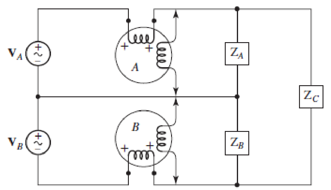
■ FIGURE 12.39
a.
Find the wattmeter readings in the circuit of Figure 12.39.
Answer to Problem 39E
The reading of wattmeter
Explanation of Solution
Given data:
The load impedance are
Calculation:
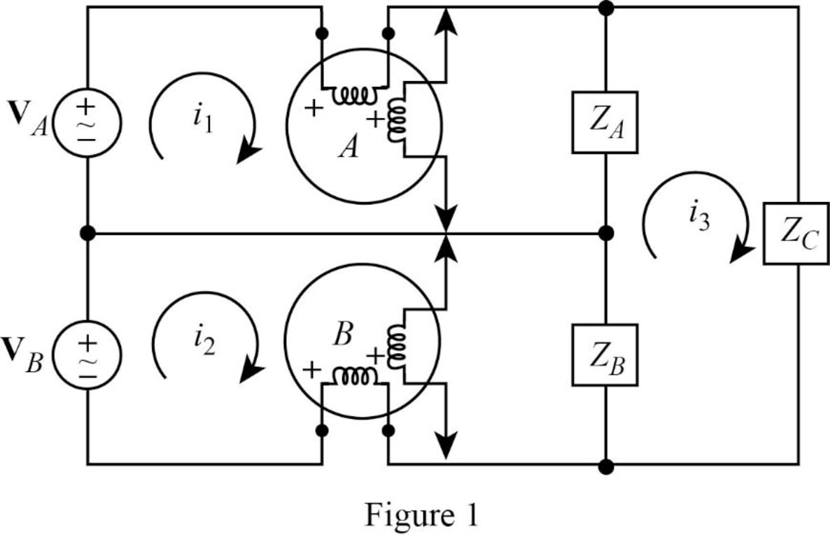
The given figure with mesh currents is shown in Figure 1.
Apply Kirchhoff’s voltage law to the loop with current
Apply Kirchhoff’s voltage law to the loop with current
Apply Kirchhoff’s voltage law to the loop with current
Rearrange equation (1).
Substitute equation (4) in (3).
Simplify the equation as follows.
Substitute equation (5) in (4).
Substitute equation (6) in (2).
Simplify the equation as follows.
Substitute
Substitute
Calculate the power delivered by phase A as follows.
Calculate the power delivered by phase B as follows.
Conclusion:
Thus, the reading of wattmeter
b.
Verify that the sum of the wattmeter reading is equal to the total power taken by the three loads using LTspice.
Explanation of Solution
Formula used:
Write the expression for inductive reactance.
Here,
Write the expression for capacitive reactance.
Here,
Calculation:
Let us assume that the angular frequency
Substitute
Substitute
Substitute
LTspice Simulation:
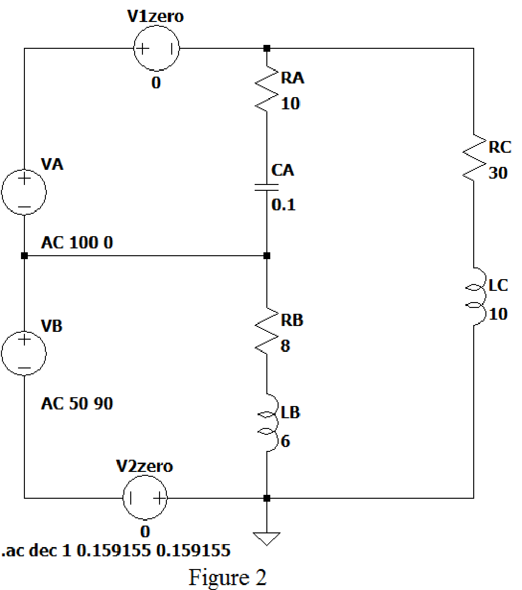
Draw the given figure in LTspice as shown in Figure 2. V1 zero and V2 zero connected in the circuit to find the current flows through it.
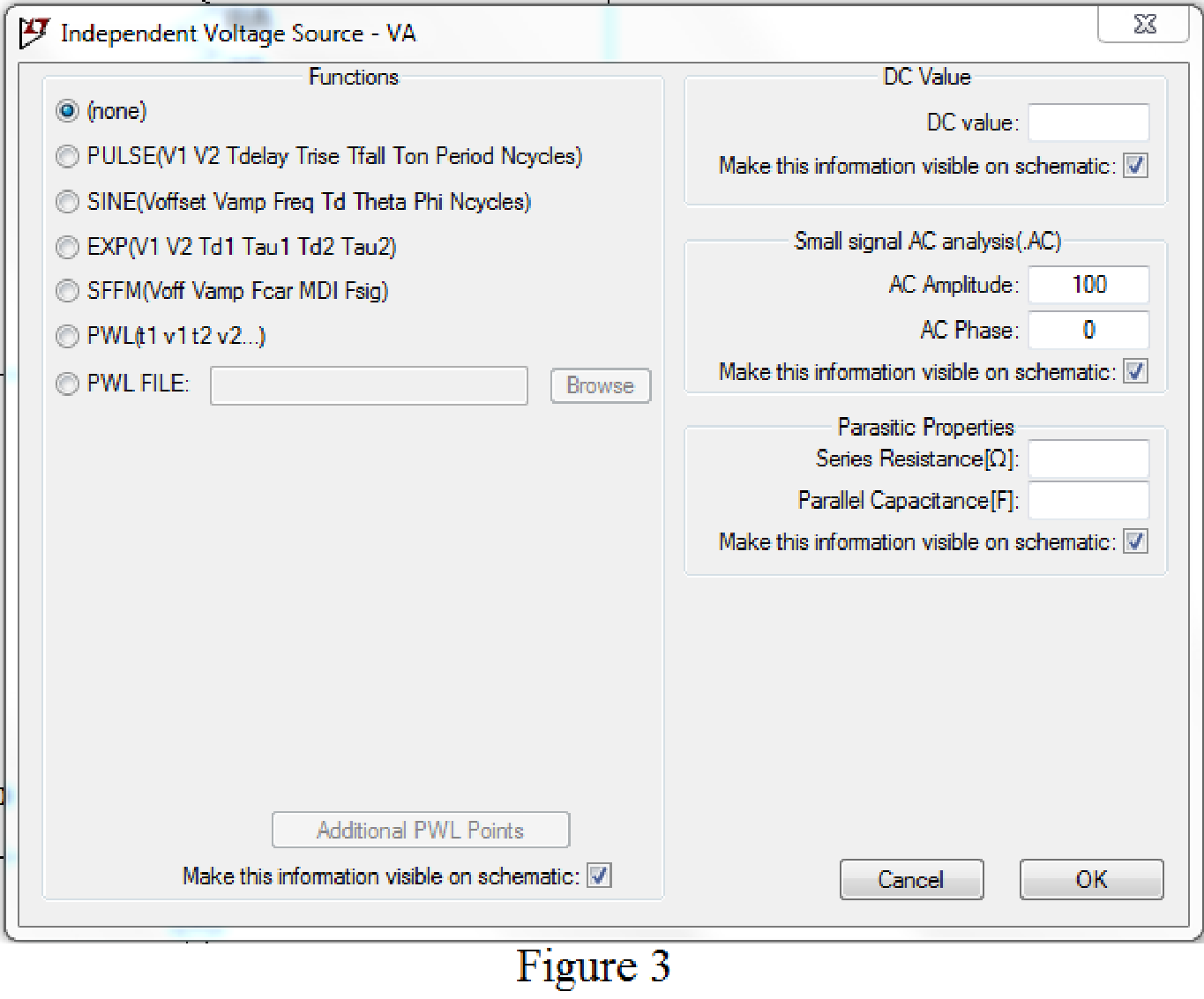
Set the values of voltages VA by right clicking on the voltage component, select none in “Functions” and enter the Small signal AC analysis parameters: AC amplitude as 100 for V1 as shown in Figure 3 for VA.
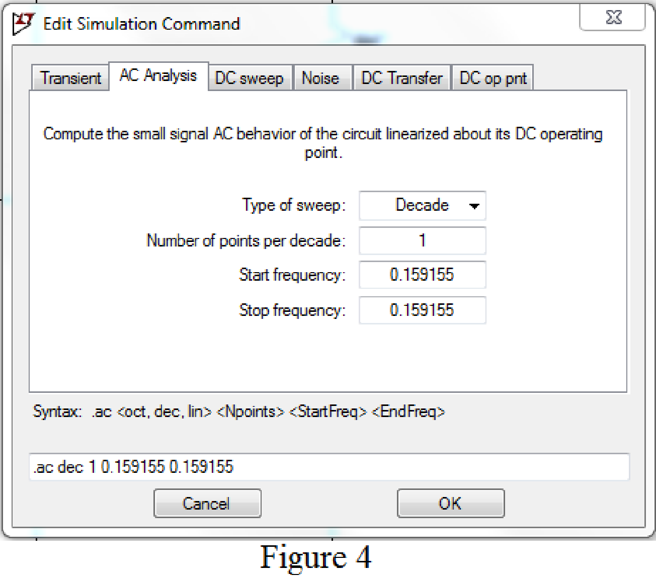
Now save the circuit, and open the “Edit Simulation command” choose AC analysis and select the sweep type as Decade, Number of points per decade 1, Start frequency and Stop frequency as 0.159155 Hz.
Now, run the simulation for the designed circuit. The output for the AC analysis will displays as shown in Figure 5.
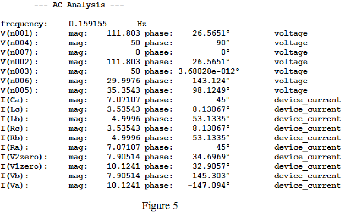
From above simulation results, the current flows through the load resistance are given below.
Calculate the power delivered to load
Calculate the power delivered to load
Calculate the power delivered to load
The total power delivered to the load is
The sum of the wattmeter reading is
Conclusion:
Thus, it is verified that sum of the wattmeter reading is equal to the total power taken by the three loads using LTspice.
Want to see more full solutions like this?
Chapter 12 Solutions
ENGINEERING CIRCUIT...(LL)>CUSTOM PKG.<


- Determine the figure of merit for both DSB AM and FM, provided that the modulating signal is a single-tone signal.arrow_forward+ Preemphasis LHS R signal L RHS signal Frequency doubler Pilot tone (a) + Preemphasis Composite baseband spectrum L+R Pilot tone L-R (DSB-SC) + FM modulator f (kHz) (b) 15 19 23 38 53 Lowpass filter Deemphasis + L Audio amplifier FM discriminator Narrowband filter Frequency doubler Bandpass R Audio ✗ Deemphasis + filter amplifier (c) and (c) FM stereo receiver. FIGURE A.25 FM stereo broadcasting: (a) FM stereo transmitter, (b) spectrum of FM stereo signal,arrow_forward4-3) Similar to Lathi & Ding, Prob. P.4.2-3 For a DSB-SC signal g(t) = 2m(t)cos(4000) transmitting each of the following messages, (a) write an expression for G(f) and (b) sketch the magnitude spectrum |G(f)], specifying the FWHM (full width at half-maximum) of any spectrum peaks. a) m(t) = sinc²(100-50л) b) m(t)=400e-80,000r²arrow_forward
- 4-2) Lathi & Ding, similar to problem 3.8-5. For the filter shown below, with an input signal whose PSD is given by S⭑(f) = П(0.25лf): (a) Find the total input power; (b) Find the transfer function H(f); (c) Find the power spectral density (PSD) of the output signal; (d) Find the total output power of the signal 500 ΚΩ d 1 µF dt y(t)arrow_forward4-1) Distortionless transmission A bandpass signal g(t) of bandwidth B = 2000 Hz centered at f= 5.0x10⁴ Hz is passed through the RC filter below with RC = 4.0x10⁵ radians/s. If over the passband, a variation of less than 2% in both amplitude response and time delay is considered to be distortionless transmission, would g(t) be transmitted without distortion? Find the approximate magnitude response and the approximate time delay for the signal. R w g(1) y(t)arrow_forwardFundamentals Of Energy Systems THQ1 Q6arrow_forward
- A single phase has two group A and B, 50 Hz, overhead line system has radius of conductor 0.5 cm. alculate the total inductance of the line. a2 a1 6 cm 2 m 3m b₂ m B b₁arrow_forwardA single phase has two group of conductors A & B; where A consists of 3- sub conductors (a, b, c) each of its have a radius of 0.25 cm, and the group B consists of two sub conductors (d, e) each of its have a radius of 0.5 cm. Calculate the inductance of the total system where the distance between the sub conductors is as below. 9m 6m 6m ୦୩ Group A Group Barrow_forwardFundamentals Of Energy Systems THQ1 Q8arrow_forward
 Introductory Circuit Analysis (13th Edition)Electrical EngineeringISBN:9780133923605Author:Robert L. BoylestadPublisher:PEARSON
 Delmar's Standard Textbook Of ElectricityElectrical EngineeringISBN:9781337900348Author:Stephen L. HermanPublisher:Cengage Learning
 Programmable Logic ControllersElectrical EngineeringISBN:9780073373843Author:Frank D. PetruzellaPublisher:McGraw-Hill Education
 Fundamentals of Electric CircuitsElectrical EngineeringISBN:9780078028229Author:Charles K Alexander, Matthew SadikuPublisher:McGraw-Hill Education
 Electric Circuits. (11th Edition)Electrical EngineeringISBN:9780134746968Author:James W. Nilsson, Susan RiedelPublisher:PEARSON
 Engineering ElectromagneticsElectrical EngineeringISBN:9780078028151Author:Hayt, William H. (william Hart), Jr, BUCK, John A.Publisher:Mcgraw-hill Education,