
Videos
For the transistors in the circuit in Figure P 12.53, the parameters are:
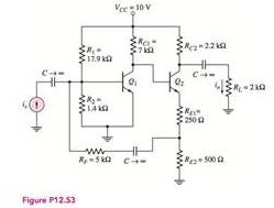
The value of the closed loop current gain of the circuit.
Answer to Problem 12.53P
The value of the current gain is
Explanation of Solution
Given:
The given diagram is shown in Figure 1
Calculation:
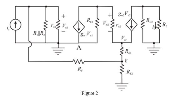
The small signal model of the above circuit is shown below.
The required diagram is shown in Figure 2
The expression to determine the value of the Thevenin resistance of the circuit is given by,
The Thevenin voltage of the circuit is calculated as,
The expression for the base current of the first transistor is given by,
Substitute
The expression to determine the collector current of the first transistor is given by,
Substitute
The expression to determine the value of the base voltage of the second transistor is given by,
Substitute
The expression for the current
Substitute
The expression to determine the value of the collector current
Substitute
The expression for the transconductance of the first transistor is given by,
Substitute
The expression for the small signal resistance is given by,
Substitute
The expression for the transconductance of the second transistor is given by,
Substitute
The expression for the small signal resistance is given by,
Substitute
Apply KCL at source
Substitute
Apply KCL at node A.
Substitute
Apply KCL at node
Substitute
Apply KCL at
Substitute
Substitute
Substitute
Substitute
Substitute
The expression to determine the value of the output current is given by,
Substitute and
Substitute
Conclusion:
Therefore, the value of the current gain is
Want to see more full solutions like this?
Chapter 12 Solutions
Microelectronics: Circuit Analysis and Design


- Q6) Find the current density J for the magnetic field intensity vectors: (a) H = x²ya, + y²zay - 2xza, (b) H = p²zap + p³a + 3pz²az sin cos (c) H = a, 2 +2arrow_forwardQ2) Line x = 0, y=0,0arrow_forwardQ4) Given the magnetic vector potential: A = y²z ax-(x + 1)z² az A/m Find(a) the magnetic flux density; (b)the magnetic flux through a square loop described by 0≤x≤1, 0 ≤ y ≤1, z=2.arrow_forwardQ5) Consider the following arbitrary fields. Find out which of them can possibly represent electrostatic or magnetostatic field in free space. (a) A = y cos axa, + (y + ea, (b) B 20 р (c) C = r² sin 0 aarrow_forwardEx. 12 plane y=l carries current k = 50āz Find at- roro) ره α)- ⑥(1.5-3). Hw marrow_forwardPlease, my dear teacher, solve the question on a piece of paper, not with artificial intelligence, then show the final matrix in the solution. Subject the Control Systemarrow_forwardAn Aluminum wire 2250Ft long cannot have a resistance greater than 0.2 ohms. What is the minimum size of wire that may be used?arrow_forwardCalculate the resistance for Aluminum wire, 8 AWG with a length of 1000 FT*arrow_forwardIntroduction The circuit of Fig. 1 is required to be modeled using a state - space representation, where 2 states will be used, based on the number of the energy - storing elements of the circuit, the capacitor and the inductor. u(t) + ΙΩ www 13 F 5 Ω it (t) www vc(t) 1 H Figure 1: LCR circuit The input signal to the circuit is the voltage u(t) in Volts and the output signal is the voltage across the capacitor, vc(t). Questions 1. Choice of system states: Choose appropriate signals for the 2 states of the system. x₁(t) = i₁(t) x₂ (t) =arrow_forward5. State transition matrix: (t), which is defined as, Calculate analytically the state transition matrix (t) = et = L¯¹{(sI – A)¯¹} Show that the answer is the following, 1 e-4t cos(√2t) - e-4 sin(√2 t) 1 e -4t √2 (t) = et -3 1 -4t sin (√2 t) e COS -4t cos (√2t) + - e sin(√2 t) 2-4t sin(√2 t)| Calculate the following: (SI - A)-1= Use the completion - in - the-square technique (CASE 3) to calculate the inverse Laplace: L¯¹{(SI - A)¯¹} =arrow_forwardA single-core cable working on 66 kV has a conductor diameter of 2 cm and the sheath of inside diameter is 10 cm. If two metallic intersheaths of diameters 5 cm, 8 cm respectively are used for grading the cable.. If the maximum electric stress is the same for each layers. 1- Find the voltage of each metallic intersheaths. 2- Find the thickness of each layers.arrow_forwardkΩarrow_forwardarrow_back_iosSEE MORE QUESTIONSarrow_forward_ios
 Introductory Circuit Analysis (13th Edition)Electrical EngineeringISBN:9780133923605Author:Robert L. BoylestadPublisher:PEARSON
 Delmar's Standard Textbook Of ElectricityElectrical EngineeringISBN:9781337900348Author:Stephen L. HermanPublisher:Cengage Learning
 Programmable Logic ControllersElectrical EngineeringISBN:9780073373843Author:Frank D. PetruzellaPublisher:McGraw-Hill Education
 Fundamentals of Electric CircuitsElectrical EngineeringISBN:9780078028229Author:Charles K Alexander, Matthew SadikuPublisher:McGraw-Hill Education
 Electric Circuits. (11th Edition)Electrical EngineeringISBN:9780134746968Author:James W. Nilsson, Susan RiedelPublisher:PEARSON
 Engineering ElectromagneticsElectrical EngineeringISBN:9780078028151Author:Hayt, William H. (william Hart), Jr, BUCK, John A.Publisher:Mcgraw-hill Education,