
To show: The variation in magnitude of the input resistance
To explain: The influence of
Answer to Problem 12.9TYU
The influence of
Explanation of Solution
Given:
The given diagram is shown in Figure 1
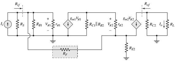
Figure 1
Feedback resistor value is varied between
Calculation:
Mark the nodes and redraw the circuit.
The given diagram is shown in Figure 2
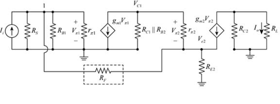
Figure 2
Mark the values and draw the PSpice circuit for the above circuit.
The required circuit is shown in Figure 3
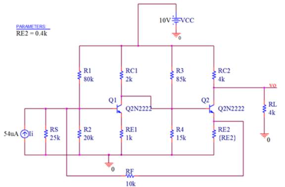
Figure 3
The snip for the drop box of the internal parameters of the transistor is shown in Figure 4
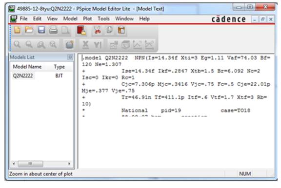
Figure 4
The simulation settings to estimate the magnitude of the current gain as the value of
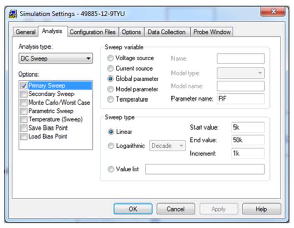
Figure 5
Then left click on the trace option then select add trace and type “ABS(V(vi)l(li))” then command in the trace magnitude of the resistance
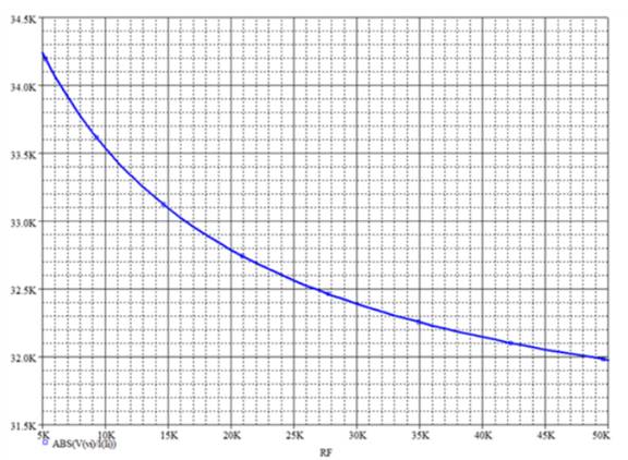
Figure 6
By KCL the expression for the current
The expression for the node voltage is given by,
Apply KCL at node
Substitute
Consider
The expression for the output current is given by,
Substitute
Substitute
Conclusion:
Therefore, the influence of
Want to see more full solutions like this?
Chapter 12 Solutions
Microelectronics: Circuit Analysis and Design
- Please draw logic circuitarrow_forwardA 220-volt, 20-horsepower compound motor (long shunt, Figure 21–16A) has an armature resistance of 0.25 ohm, series field resistance of 0.19 ohm, and shunt field resistance of 33 ohms. a. Calculate the current taken by the motor at the instant of starting if it is con-nected directly to the 220-volt line. b. Calculate the current when the motor is running if the armature is developing 184 volts counter-emf.arrow_forwardDesign a modulo-11 ripple (asynchronous) up-counter with negative edge-triggered T flip-flops and draw the corresponding logic circuit. (I)Build the state diagram and extract the state table (II)Draw the logic circuit (III)What is the maximum modulus of the counter?arrow_forward
- the diagram show 4 motor connected to a k-35 controller. I would like detail explanation to know how the circuit work. Is the controller compatible with the motor? The motor shown is series, parallel or both?arrow_forwardplease draw logic diagram pleasearrow_forwardPlease draw the diagrams please thank youarrow_forward
- A plane wave propagating through a medium with &,,-8 μr = 2 has: E = 0.5 e-j0.33z sin (108 t - ẞz) ax V/m. Determine (a) ẞ (b) The loss tangent (c) Wave impedance (d) Wave velocity (e) H fieldarrow_forward2) The phase voltage at the terminals of a balanced three-phase Y-connected load is 2400 V. The load has an impedance of 16+j12 2/6 and is fed from a line having an impedance of 0.10+j0.80 2/6. The Y- connected source at the sending end of the line has a positive phase sequence and an internal impedance of 0.02+j0.16 2/6. Use the a-phase voltage at the load as the reference. a) Construct the a-phase equivalent circuit of the system b) Calculate the line currents IaA, IbB, and Icc c) Calculate the phase voltages at the terminals of the source, Van, Vbn, Vcn- d) Calculate the line voltages at the source, Vab, Vbc and Vca. e) Calculate the internal phase-to-neutral voltages at the source, Va'n, Vb'n, Ve'n,arrow_forward1) • A balanced three-phase circuit has the following characteristics: Y-Y connected The line voltage at the source is Vab = 120√3(0°V • The phase sequence is positive The line impedance is 2+ j3 2/0 The load impedance is 28 + j37 02/0 a) [4 pts] Draw the single phase equivalent circuit for the a-phase. b) [2 pts] Calculate the line current IaA in the a-phase. c) [4 pts] Calculate the line voltage VAB at the load in the a-phase.arrow_forward
- Find the value of V0 using the superposition method. Note: The answer is V0=-428.57mvarrow_forwardDon't use ai to answer I will report you answerarrow_forwardIf a trolley has a 120VDC power supply intended to power auxiliary components such as lights, buzzers, and speakers, how would the speakers connect to that power system? I understand that speakers typically operate on AC, so what is the most efficient way to connect them to the 120VDC setup? Additionally, could you provide an estimate of the power output for the speakers?arrow_forward
 Introductory Circuit Analysis (13th Edition)Electrical EngineeringISBN:9780133923605Author:Robert L. BoylestadPublisher:PEARSON
 Delmar's Standard Textbook Of ElectricityElectrical EngineeringISBN:9781337900348Author:Stephen L. HermanPublisher:Cengage Learning
 Programmable Logic ControllersElectrical EngineeringISBN:9780073373843Author:Frank D. PetruzellaPublisher:McGraw-Hill Education
 Fundamentals of Electric CircuitsElectrical EngineeringISBN:9780078028229Author:Charles K Alexander, Matthew SadikuPublisher:McGraw-Hill Education
 Electric Circuits. (11th Edition)Electrical EngineeringISBN:9780134746968Author:James W. Nilsson, Susan RiedelPublisher:PEARSON
 Engineering ElectromagneticsElectrical EngineeringISBN:9780078028151Author:Hayt, William H. (william Hart), Jr, BUCK, John A.Publisher:Mcgraw-hill Education,


