
Videos
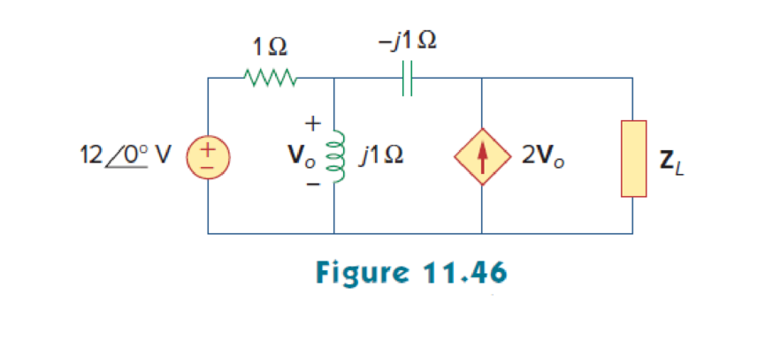
In the circuit of Fig. 11.46, find the value of ZL that will absorb the maximum power and the value of the maximum power.
Find the value of the load impedance
Answer to Problem 15P
The value of load impedance
Explanation of Solution
Given data:
Refer to Figure 11.46 in the textbook.
The inductance
The capacitance C is
The source voltage is
Formula used:
Write the expression to find the maximum average power.
Here,
Write the general expression for load impedance
Calculation:
Refer to Figure 11.46 in the textbook.
In the circuit, to calculate the Thevenin impedance
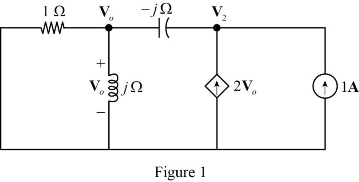
In Figure 1, apply Kirchhoff’s currrent law at node voltage
Rearrange the equation as follows,
In Figure 1, apply Kirchhoff’s currrent law at node voltage
Rearrange the equation as follows,
Substitute equation (3) in equation (4) to find
Rearrange the equation as follows,
The Thevenin impedance is,
Substitute
Simplify the equation as follows,
For maximum average power transfer, the load impedance
On comparing the equation with equation (2),
The given circuit of Figure 11.46 is modified as shown in Figure 2.
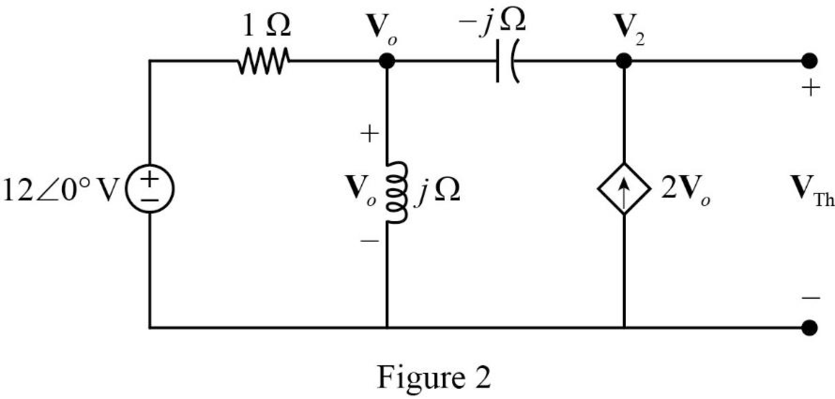
In Figure 2, apply Kirchhoff’s current law at node voltage
Rearrange the equation as follows,
In Figure 2, apply Kirchhoff’current law at node voltage
Rearrange the equation as follows,
Substitute
The voltage
Convert the equation from rectangular to polar form.
The Thevenin voltage,
Substitute
Conclusion:
Thus, The value of load impedance
Want to see more full solutions like this?
Chapter 11 Solutions
Fundamentals of Electric Circuits
Additional Engineering Textbook Solutions
Starting Out with Java: From Control Structures through Objects (7th Edition) (What's New in Computer Science)
SURVEY OF OPERATING SYSTEMS
Thermodynamics: An Engineering Approach
Modern Database Management
Concepts Of Programming Languages
Electric Circuits. (11th Edition)


- A.With the aid of a diagram, describe fringing, and explain the impact that it has on the relevant magnetic circuit parameter. B. A coil of 1500 turns give rise to a magnetic flux of 2.5 mWb when carrying a certain current. If this current is reversed in 0.2 s, what is the average value of the e.m.f. induced in the coil? C.Define Mutual Inductance.Two coils are connected in series and their total inductance is measured as 0.12 H, and when the connection to one coil is reversed, the total inductance is measured as 0.04 H. If the coefficient of coupling is 0.8, determine:The self-inductance of each coil, and the mutual inductance between the coils.arrow_forwardcomparing Lenz's law and the left hand generator rule, which of these is the more important fundamental principle?arrow_forwardExample: Electric Field and Potential Inside a Charged Sphere Problem: A sphere of radius R = 0.2 m is uniformly charged with a total charge Q = 5 μC. The sphere is made of a dielectric material with relative permittivity € = 4. Calculate: 1. The electric field intensity E(r) inside and outside the sphere. 2. The electric potential (r) at any point inside the sphere. Solution: Step 1: Given Data Radius of the sphere: R = 0.2m, Total charge: Q-5 μC=5× 10° C. Step 2: Electric Field Inside the Sphere (< Using Gauss's Law:arrow_forwardplease remember to draw the circuitsarrow_forwardA balanced three-phase, A - connected induction motor consumes 3246 W when the l voltage is 208 V, and the line current is 10.6 A. Calculate: i. The motor's winding resistance. ii. The motor's winding reactance. 12 marrow_forwarda) An iron ring, having a mean circumference of 250 mm and a cross-sectional area of 400 mm², is wound with a coil of 70 turns. Using the following data, calculate the current required to set up a flux of 510µWb in the ring. H (A/m) 350 600 1250 B (T) 1.0 1.2 1.4 b) Calculate also: i. The inductance of the coil at the current obtained in Question 2 (a) above. ii. The self-induced e.m.f. if this current is switched off in 0.005 s. Assume that there is no residual flux.arrow_forwardarrow_back_iosSEE MORE QUESTIONSarrow_forward_ios
 Introductory Circuit Analysis (13th Edition)Electrical EngineeringISBN:9780133923605Author:Robert L. BoylestadPublisher:PEARSON
 Delmar's Standard Textbook Of ElectricityElectrical EngineeringISBN:9781337900348Author:Stephen L. HermanPublisher:Cengage Learning
 Programmable Logic ControllersElectrical EngineeringISBN:9780073373843Author:Frank D. PetruzellaPublisher:McGraw-Hill Education
 Fundamentals of Electric CircuitsElectrical EngineeringISBN:9780078028229Author:Charles K Alexander, Matthew SadikuPublisher:McGraw-Hill Education
 Electric Circuits. (11th Edition)Electrical EngineeringISBN:9780134746968Author:James W. Nilsson, Susan RiedelPublisher:PEARSON
 Engineering ElectromagneticsElectrical EngineeringISBN:9780078028151Author:Hayt, William H. (william Hart), Jr, BUCK, John A.Publisher:Mcgraw-hill Education,