
Concept explainers
Videos
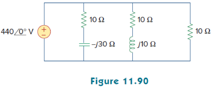
Consider the power system shown in Fig. 11.90. Calculate:
- (a) the total complex power
- (b) the power factor
- (c) the parallel capacitance necessary to establish a unity power factor
(a)
Calculate the complex power of the circuit shown in Figure 11.90.
Answer to Problem 75P
The total complex power for the given circuit is
Explanation of Solution
Given data:
Refer to Figure 11.90 in the textbook.
The voltage
The capacitance C is
The inductance L is
Formula used:
Write the expression to find the complex power.
Here,
Write the expression to find the complex power.
Here,
Calculation:
Refer to figure 11.90 in the textbook.
Consider the impedance
Consider the impedance
Consider the impedance
Substitute
Substitute
Substitute
The total complex power is,
Substitute
Comparing the above equation with equation (1).
Hence, the total complex power is,
Conclusion:
Thus, the total complex power for the given circuit is
(b)
Find the power factor for the given circuit.
Answer to Problem 75P
The power factor for the given circuit is
Explanation of Solution
Given data:
The voltage
From Part (a),
The real power and the reactive power is,
Formula used:
Write the expression to find the power factor
Here,
Write the expression for phase angle
Calculation:
Substitute
Substitute
Conclusion:
Thus, the power factor for the given circuit is
(c)
Find the parallel capacitance value required to establish a unity power factor.
Answer to Problem 75P
The value of capacitance is
Explanation of Solution
Given data:
The voltage
Formula used:
Write the expression to find the value of the capacitance.
Here,
Calculation:
Consider the frequency is
From equation (3), the reactive power is,
Substitute
Simplify the equation as follows,
Conclusion:
Thus, the value of capacitance is
Want to see more full solutions like this?
Chapter 11 Solutions
Fundamentals of Electric Circuits


- MacBook Air J GE F11 + "/ F12 (25) Determine how 20. (45pts) A battery operated sensor transmits to a receiver that is plugged in to a power outlet. The device is continuously operated. The battery is a commercially available 9 V battery with a 1.1 AmpHr capacity. The application requires a bit rate of 120 Mbps and an error rate of less than 10^-5. The channel has a center frequency of 5.8 GHz, a bandwidth of 20 MHz and a noise power spectral density of 10^-12 W/Hz. The maximum distance is 50 meters and the losses in the channel attenuates the signal by 0.05 dB/meter. M-ary FSK is not possible due to bandwidth limitations. a) (5pts) To maximize battery life, what modulation scheme would you use?arrow_forwardCan you please provide an explanation and working. The solution is provided.arrow_forwardplease show working and an explanation. The ans is 20.68 ms.arrow_forward
- A 400V,50Hz,Y-connected, 4-pole,three-phase wound rotor induction motor, the rotor circuit is Y- connected with R2=0.1, X2= 0.8 Q/ph .The measured e.m.f between two slip rings at 1440 rpm is 165 V. If the total stator losses are 650 W,find:airgap power, rotor copper loss, input power, developed (or gross) mechanical power, output power, efficiency, if friction and windage losses are 377W?arrow_forwardconsider the circuit below. Assume it uses ideal diodes with the details specified above. the left side of the circuit is basically a wheatstone bridge, hooked to the right side, which is a differential op amp. a) what is the voltage between junctions "A" and "B" if R2 is 201 ohms? b) what are the minimum and maximum values of R2 can be without the op amp hitting saturation?remember that for the diodes to be ideal you they have to have a turn on voltage of 0.6 volts.arrow_forwardThe capacitors in the circuit shown below have no energy stored in them and then switch “S1” closes at time t=0. Assume the ideal op amp does not saturate. As stated above assume the diodes are ideal with parameters specified above. Diodes are at 0.6 Volts Show the derivations of the mathematical equations for v(t) at Locations A and B for t≥ 0arrow_forward
- Phase (deg) Magnitude (dB) -20 -40 -60 -80 -100 ° -90 -180 -270 10-1 (i) ° Problem 5 Consider a unity (negative) feedback system with a proportional controller. The Bode plot of the plant transfer function G(s) is given as below. System: sys Frequency (rad/s): 1 Magnitude (dB): 13.9 System: sys Frequency (rad/s): 14.9 Magnitude (dB): 6.58 System: sys Frequency (rad/s): 1 Phase (deg): -9.76 10° System: sys Frequency (rad/s): 25.6 Magnitude (dB): -0.0703 System: sys Frequency (rad/s): 41.3 Magnitude (dB): -8.06 System: sys Frequency (rad/s): 200 Magnitude (dB): -44.4 System: sys Frequency (rad/s): 14.9 Phase (deg): -110 System: sys Frequency (rad/s): 25.6 Phase (deg): -148 System: sys Frequency (rad/s): 41.3 Phase (deg): -180 System: sys Frequency (rad/s): 200 Phase (deg): -247 101 Frequency (rad/s) 102 Find the gain crossover frequency, phase crossover frequency, gain margin and phase margin of the system. Is the closed-loop system stable? (ii) What is the steady-state error of the…arrow_forwardsolve and show in detail all calculationsarrow_forwardsolve and show in detail all calculationsarrow_forward
- solve and show in detail all calculationsarrow_forwardProblem 1 Consider the following system. In the figure, y(t) denotes the voltage across the capacitor. u(t) 1+ R W L + 0000 y(t) C Y(s) (i) Find the transfer function H(s): = of the system. U(s) Now suppose, R 10 KQ, L = 0.5 mH and C = 10 μF. (ii) Find the poles and zeros. Is the system BIBO stable? (iii) Compute settling time, rise time, peak time and % overshoot of the step response of the system. What the steady-state output for unit step input?arrow_forwardA 3-phase, 52 H.P, 50 Hz, 6-Pole, Y- connected induction motor runs at a speed of 980 rpm.The motor is supplied from 380 V mains and it takes a rated current of 80 A at 0.8 p.f. If the total stator losses are 1.7 kW, determine: the air-gap power, rotor copper loss, friction and windage losses?arrow_forward
 Power System Analysis and Design (MindTap Course ...Electrical EngineeringISBN:9781305632134Author:J. Duncan Glover, Thomas Overbye, Mulukutla S. SarmaPublisher:Cengage Learning