
Videos
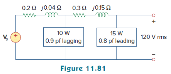
For the circuit in Fig. 11.81, find Vs.
Find the voltage
Answer to Problem 62P
The voltage
Explanation of Solution
Given data:
Refer to Figure 11.81 in the textbook.
The voltage
For load A,
The real power
The power factor
For load B,
The real power
The power factor
Formula used:
Write the expression to find the complex power.
Here,
Write the expression to find the power factor
Here,
Write the expression to find the real power.
Write the expression to find the reactive power.
Write the expression to find the output voltage.
Calculation:
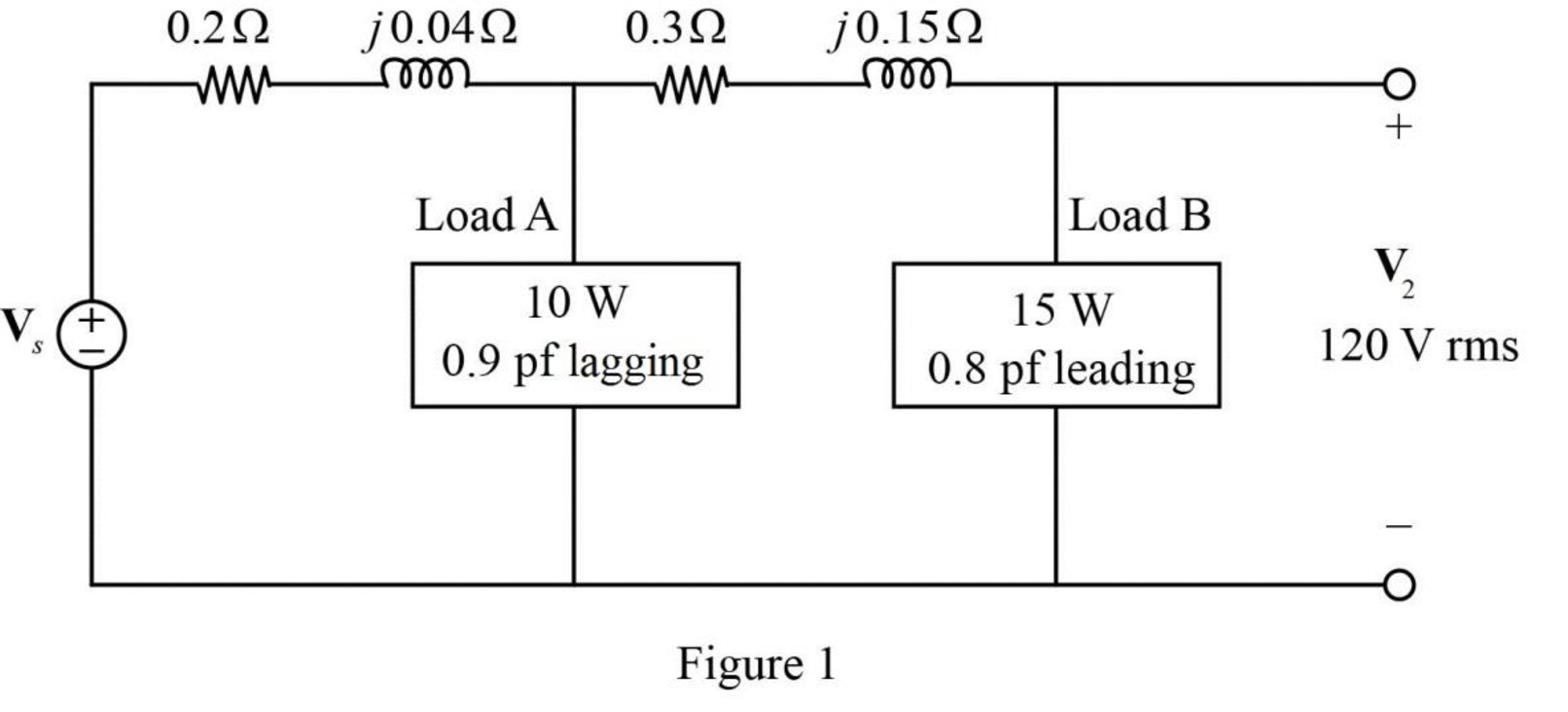
The given Figure 11.81 is redrawn as shown in Figure 1.
For load A:
Substitute
Substitute
Rearrange the equation as follows,
Substitute
Substitute
For load B:
Substitute
Substitute
Rearrange the equation as follows,
Substitute
Substitute
As the power factor is leading, the load is capacitive. Therefore, the equation becomes,
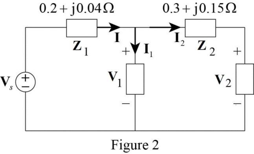
The modified Figure is shown in Figure 2.
Substitute
The voltage
Substitute
Substitute
Convert the equation from polar to rectangular form.
The current
Substitute
The voltage supplied by the source is,
Substitute
Convert the equation from rectangular to polar form.
Conclusion:
Thus, the voltage
Want to see more full solutions like this?
Chapter 11 Solutions
Fundamentals of Electric Circuits


- Chapter 14, Problem 69. end Design the filter in Fig. 14.94 to meet the following requirements: (a) It must attenuate a signal at 2 kHz by 3 dB compared with its value at 10 MHz. (b) It must provide a steady-state output of v。 (t) input v, (t)=4sin(2 × 10⁸t) V. = 10 sin(2x 10⁸t+ 180°) V for an Rf ww R ww C 1+ Vs Figure 14.94 For Prob. 14.69.arrow_forwardChapter 14, Problem 15. Construct the Bode magnitude and phase plots for 40(s+1) H(s) (s + 2)(s+10) s=j@arrow_forwardA series RLC network has R = 2 kQ, L = 40 mH, and C = 1 μ F. Calculate the impedance at resonance and at one-fourth, one-half, twice, and four times the resonant frequency.arrow_forward
- Chapter 14, Problem 5. For each of the circuits shown in Fig. 14.72, find H(s) = V。 (s)/V¸(s). R www V. R L Vo Vs m R (a) www (b) Figure 14.72 For Prob. 14.5. + CV₂arrow_forwardA robot gripper is shown on Fig.1a. The block diagram of the control system is shown in Fig.1b. This system is conditionally stable because it is stable only for a range of the gain K. Using the Routh-Hurwitz criterion method to determine the range of gain for which the system is stable. Find the steady-state error due to unit step input. Sketch the root locus of the system and analyze its stability. Find the value of K so that the phase margin is minimum, and record the values of the phase margin, gain margin, Mr, and BW. Then draw the Bode plot of the system and discuss its stability using the Nyquist stability method. What is the value of this maximum overshoot for both large and small values of K due to unit step input? Draw the response of the open-loop and closed-loop of the system according to the unit step system for k=15, 25, 50. Discuss how to improve the system response if needed.arrow_forwardPlease show the stepsarrow_forward
- Don't use ai to answer I will report you answerarrow_forwardDerive the transfer functions C'A(s)/T'(s) and T'(s)/C'A0(s). show step by step and write them out so they are easy to read. thank youarrow_forward4) Find the Norton equivalent of the following circuit. 5 µF 4 cos(200t+30°) A ele 10 H www 2 ΚΩ barrow_forward
- Don't use ai to answer I will report you answerarrow_forwardQ1. Consider the unity feedback control system whose open-loop transfer function is: G(s) = = 40(S + 2) s(s+3)(s + 1)(s + 10) hod of Ziegler-Nichols. By using second method of Ziegler- Nichols, calculate the PID, PI-D and I-PD parameters and make tuning for this for this parameters to get accepting response for the following system, then compare your results for all types controllers? GINarrow_forward1) Use the method of source transformation to find Ix in the following circuit. ΖΩ j4Ω wwwm -j20 60/0° V(+ 602 www 492 -j30 wwwarrow_forward
 Delmar's Standard Textbook Of ElectricityElectrical EngineeringISBN:9781337900348Author:Stephen L. HermanPublisher:Cengage Learning