
Fundamentals of Electric Circuits
6th Edition
ISBN: 9780078028229
Author: Charles K Alexander, Matthew Sadiku
Publisher: McGraw-Hill Education
expand_more
expand_more
format_list_bulleted
Concept explainers
Videos
Textbook Question
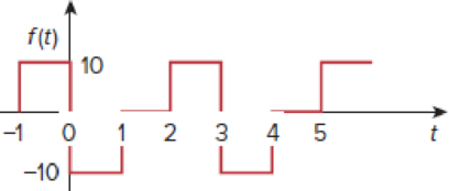
Chapter 11, Problem 25P
Find the rms value of the signal shown in Fig. 11.56.
Figure 11.56
Expert Solution & Answer

Trending nowThis is a popular solution!

Students have asked these similar questions
If Fourier transform of f(t) is F(w) find Fourier transform of g(t) using
only properties.
d
g(t) = f(2t)+8(3-1)+ ej(t-1)f(t)
dt
3z²+7z+1
dz
(b) If C is the circle |z+i|=1.
What is the value of S
(a) If C is the circle |z+1|=1.
z+1
(c) If C is the ellipse x²+y2=8.
=
Find the residues of all the poles of f(z) =
3z
(z+2)²(z²-1)
Chapter 11 Solutions
Fundamentals of Electric Circuits
Ch. 11.2 - Calculate the instantaneous power and average...Ch. 11.2 - A current A flows through an impedance Find the...Ch. 11.2 - In the circuit of Fig. 11.4, calculate the average...Ch. 11.2 - Calculate the average power absorbed by each of...Ch. 11.3 - For the circuit shown in Fig. 11.10, find the load...Ch. 11.3 - In Fig. 11.12, the resistor RL is adjusted until...Ch. 11.4 - Find the rms value of the current waveform of Fig....Ch. 11.4 - Find the rms value of the full-wave rectified sine...Ch. 11.5 - Prob. 9PPCh. 11.5 - Prob. 10PP
Ch. 11.6 - For a load, Determine: (a) the complex and...Ch. 11.6 - A sinusoidal source supplies 100 kVAR reactive...Ch. 11.7 - In the circuit in Fig. 11.25, the 60- resistor...Ch. 11.7 - Two loads connected in parallel are respectively 3...Ch. 11.8 - Find the value of parallel capacitance needed to...Ch. 11.9 - For the circuit in Fig. 11.33, find the wattmeter...Ch. 11.9 - The monthly reading of a paper mills meter is as...Ch. 11.9 - An 500-kW induction furnace at 0.88 power factor...Ch. 11 - The average power absorbed by an inductor is zero,...Ch. 11 - The Thevenin impedance of a network seen from the...Ch. 11 - The amplitude of the voltage available in the...Ch. 11 - If the load impedance is 20 j20, the power factor...Ch. 11 - A quantity that contains all the power information...Ch. 11 - Reactive power is measured in: (a) watts (b) VA...Ch. 11 - In the power triangle shown in Fig. 11.34(a), the...Ch. 11 - For the power triangle in Fig. 11.34(b), the...Ch. 11 - A source is connected to three loads Z1, Z2, and...Ch. 11 - The instrument for measuring average power is the:...Ch. 11 - If v(t) = 160 cos 50t V and i(t) = 33 sin (50t ...Ch. 11 - Given the circuit in Fig. 11.35, find the average...Ch. 11 - A load consists of a 60- resistor in parallel with...Ch. 11 - Using Fig. 11.36, design a problem to help other...Ch. 11 - ssuming that vs = 8 cos(2t 40) V in the circuit...Ch. 11 - For the circuit in Fig. 11.38, is = 6 cos 103t A....Ch. 11 - Given the circuit of Fig. 11.39, find the average...Ch. 11 - In the circuit of Fig. 11.40, determine the...Ch. 11 - For the op amp circuit in Fig. 11.41, Find the...Ch. 11 - In the op amp circuit in Fig. 11.42, find the...Ch. 11 - For the network in Fig. 11.43, assume that the...Ch. 11 - For the circuit shown in Fig. 11.44, determine the...Ch. 11 - The Thevenin impedance of a source is ZTh = 120 +...Ch. 11 - Using Fig. 11.45, design a problem to help other...Ch. 11 - In the circuit of Fig. 11.46, find the value of ZL...Ch. 11 - For the circuit in Fig. 11.47, find the value of...Ch. 11 - Calculate the value of ZL in the circuit of Fig....Ch. 11 - Find the value of ZL in the circuit of Fig. 11.49...Ch. 11 - The variable resistor R in the circuit of Fig....Ch. 11 - The load resistance RL in Fig. 11.51 is adjusted...Ch. 11 - Assuming that the load impedance is to be purely...Ch. 11 - Find the rms value of the offset sine wave shown...Ch. 11 - Using Fig. 11.54, design a problem to help other...Ch. 11 - Determine the rms value of the waveform in Fig....Ch. 11 - Find the rms value of the signal shown in Fig....Ch. 11 - Find the effective value of the voltage waveform...Ch. 11 - Calculate the rms value of the current waveform of...Ch. 11 - Find the rms value of the voltage waveform of Fig,...Ch. 11 - Calculate the effective value of the current...Ch. 11 - Compute the rms value of the waveform depicted in...Ch. 11 - Find the rms value of the signal shown in Fig....Ch. 11 - Obtain the rms value of the current waveform shown...Ch. 11 - Determine the rms value for the waveform in Fig....Ch. 11 - Find the effective value f(t) defined in Fig....Ch. 11 - One cycle of a periodic voltage waveform is...Ch. 11 - Calculate the rms value for each of the following...Ch. 11 - Design a problem to help other students better...Ch. 11 - For the power system in Fig. 11.67, find: (a) the...Ch. 11 - An ac motor with impedance ZL = 2 + j 1.2 is...Ch. 11 - Design a problem to help other students better...Ch. 11 - Obtain the power factor for each of the circuits...Ch. 11 - A 110-V rms, 60-Hz source is applied to a load...Ch. 11 - Design a problem to help other students understand...Ch. 11 - Find the complex power delivered by vs to the...Ch. 11 - The voltage across a load and the current through...Ch. 11 - For the following voltage and current phasors,...Ch. 11 - For each of the following cases, find the complex...Ch. 11 - Determine the complex power for the following...Ch. 11 - Find the complex power for the following cases:...Ch. 11 - Obtain the overall impedance for the following...Ch. 11 - For the entire circuit in Fig. 11.70, calculate:...Ch. 11 - In the circuit of Fig. 11.71, device A receives 2...Ch. 11 - In the circuit of the Fig. 11.72, load A receives...Ch. 11 - For the network in Fig. 11.73, find the complex...Ch. 11 - Using Fig. 11.74, design a problem to help other...Ch. 11 - Obtain the complex power delivered by the source...Ch. 11 - For the circuit in Fig. 11.76, find the average,...Ch. 11 - Obtain the complex power delivered to the 10-k...Ch. 11 - Calculate the reactive power in the inductor and...Ch. 11 - For the circuit in Fig. 11.79, find Vo and the...Ch. 11 - Given the circuit in Fig. 11.80, find Io and the...Ch. 11 - For the circuit in Fig. 11.81, find Vs.Ch. 11 - Find Io in the circuit of Fig. 11.82. Figure 11.82Ch. 11 - Determine Is in the circuit of Fig. 11.83, if the...Ch. 11 - In the op amp circuit of Fig. 11.84, vs = 4 cos...Ch. 11 - Obtain the average power absorbed by the 10-...Ch. 11 - For the op amp circuit in Fig. 11.86, calculate:...Ch. 11 - Compute the complex power supplied by the current...Ch. 11 - Refer to the circuit shown in Fig. 11.88. (a) What...Ch. 11 - Design a problem to help other students better...Ch. 11 - Three loads are connected in parallel to a rms...Ch. 11 - Two loads connected in parallel draw a total of...Ch. 11 - A 240-V rms 60-Hz supply serves a load that is 10...Ch. 11 - A 120-V rms 60-Hz source supplies two loads...Ch. 11 - Consider the power system shown in Fig. 11.90....Ch. 11 - Obtain the wattmeter reading of the circuit in...Ch. 11 - What is the reading of the wattmeter in the...Ch. 11 - Find the wattmeter reading of the circuit shown in...Ch. 11 - Determine the wattmeter reading of the circuit in...Ch. 11 - The circuit of Fig. 11.95 portrays a wattmeter...Ch. 11 - Design a problem to help other students better...Ch. 11 - A 240-V rms 60-Hz source supplies a parallel...Ch. 11 - Oscilloscope measurements indicate that the peak...Ch. 11 - A consumer has an annual consumption of 1200 MWh...Ch. 11 - A regular household system of a single-phase...Ch. 11 - A transmitter delivers maximum power to an antenna...Ch. 11 - In a TV transmitter, a series circuit has an...Ch. 11 - A certain electronic circuit is connected to a...Ch. 11 - An industrial heater has a nameplate that reads:...Ch. 11 - A 2000-kW turbine-generator of 0.85 power factor...Ch. 11 - The nameplate of an electric motor has the...Ch. 11 - As shown in Fig. 11.97, a 550-V feeder line...Ch. 11 - A factory has the following four major loads: A...Ch. 11 - A 1-MVA substation operates at full load at 0.7...Ch. 11 - Prob. 95CPCh. 11 - A power amplifier has an output impedance of 40 +...Ch. 11 - A power transmission system is modeled as shown in...
Knowledge Booster


Learn more about
Need a deep-dive on the concept behind this application? Look no further. Learn more about this topic, electrical-engineering and related others by exploring similar questions and additional content below.Similar questions
- find the inverse Laplace transform of X(s)= i) Re[s]> 3 ii) Re[s]<1 s+5 for (s-1)(s-2)(s-3) iii) 1arrow_forwardFor R1, what is the resistance in kΩ? For R1, what the current in mA? For R1, what is the voltage in V? For R1, what is the power in W? For R2, what is the resistance in kΩ? For R2, what the current in mA? For R2, what is the voltage in V? For R2, what is the power in W? For R3, what is the resistance in kΩ? For R3, what the current in mA? For R3, what is the voltage in V? For R3, what is the power in W? For R4, what is the resistance in kΩ? For R4, what the current in mA? For R4, what is the voltage in V? For R4, what is the power in W? For R5, what is the resistance in kΩ? For R5, what the current in mA? For R5, what is the voltage in V? For R5, what is the power in W? What is the total resistance in Ω? What is the total current in mA? What is the total voltage in V? What is the total power in W?arrow_forwardPlease answer allarrow_forwardarrow_back_iosSEE MORE QUESTIONSarrow_forward_ios
Recommended textbooks for you
 Introductory Circuit Analysis (13th Edition)Electrical EngineeringISBN:9780133923605Author:Robert L. BoylestadPublisher:PEARSON
 Delmar's Standard Textbook Of ElectricityElectrical EngineeringISBN:9781337900348Author:Stephen L. HermanPublisher:Cengage Learning
 Programmable Logic ControllersElectrical EngineeringISBN:9780073373843Author:Frank D. PetruzellaPublisher:McGraw-Hill Education
 Fundamentals of Electric CircuitsElectrical EngineeringISBN:9780078028229Author:Charles K Alexander, Matthew SadikuPublisher:McGraw-Hill Education
 Electric Circuits. (11th Edition)Electrical EngineeringISBN:9780134746968Author:James W. Nilsson, Susan RiedelPublisher:PEARSON
 Engineering ElectromagneticsElectrical EngineeringISBN:9780078028151Author:Hayt, William H. (william Hart), Jr, BUCK, John A.Publisher:Mcgraw-hill Education,
Introductory Circuit Analysis (13th Edition)
Electrical Engineering
ISBN:9780133923605
Author:Robert L. Boylestad
Publisher:PEARSON
Delmar's Standard Textbook Of Electricity
Electrical Engineering
ISBN:9781337900348
Author:Stephen L. Herman
Publisher:Cengage Learning
Programmable Logic Controllers
Electrical Engineering
ISBN:9780073373843
Author:Frank D. Petruzella
Publisher:McGraw-Hill Education
Fundamentals of Electric Circuits
Electrical Engineering
ISBN:9780078028229
Author:Charles K Alexander, Matthew Sadiku
Publisher:McGraw-Hill Education
Electric Circuits. (11th Edition)
Electrical Engineering
ISBN:9780134746968
Author:James W. Nilsson, Susan Riedel
Publisher:PEARSON
Engineering Electromagnetics
Electrical Engineering
ISBN:9780078028151
Author:Hayt, William H. (william Hart), Jr, BUCK, John A.
Publisher:Mcgraw-hill Education,
What is an electric furnace and how does it work?; Author: Fire & Ice Heating and Air Conditioning Inc;https://www.youtube.com/watch?v=wjAWecPGi0M;License: Standard Youtube License