
Fundamentals of Electric Circuits
6th Edition
ISBN: 9780078028229
Author: Charles K Alexander, Matthew Sadiku
Publisher: McGraw-Hill Education
expand_more
expand_more
format_list_bulleted
Videos
Textbook Question
Chapter 11, Problem 35P
One cycle of a periodic voltage waveform is depicted in Fig. 11.66. Find the effective value of the voltage. Note that the cycle starts at t = 0 and ends at t = 6 s.
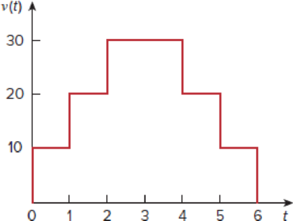
Figure 11.66
Expert Solution & Answer
Want to see the full answer?
Check out a sample textbook solution
Students have asked these similar questions
Can you rewrite the solution because it is
unclear?
Q2
AM
①(+) = 8 (1+0.5 cos 1000πt +0.5 ros 2000kt)
$4+) = 45
=
*cos 10000 πt.
8 cos wat + 4 cosat + 4 cos Wat coswet.
j1000016
+4e
-j10000πt j11000Rt
j gooort -j 9000 πt
+
e
+e
j sooort
te
+e
J11000 t
+ e
te
j 12000rt.
-J12000 kt
+ с
= 8th S(W- 100007) + 8 IS (W-10000)
<&(w) =
USB
-5-5
-4-5-4
b) Pc 2² = 64
PSB =
42
+ 4
2
Pt Pc+ PSB =
y = Pe
c) Puss =
PLSB =
= 32
4² = 8 w
32+ 8 =
× 100% = 140
(1)³×2×2
31
= 20%
x 2 = 3w
302
USB
4.5 5 5.6 6
ms Ac = 4 mi
= 0.5
mz Ac = 4
५
M2
=
=0.5
A. Draw the waveform for the following binary sequence using Bipolar RZ, Bipolar NRZ, and
Manchester code.
Data sequence= (00110100)
B. In a binary PCM system, the output signal-to-quantization ratio is to be hold to a minimum of
50 dB. If the message is a single tone with fm-5 kHz. Determine:
1) The number of required levels, and the corresponding output signal-to-quantizing noise ratio.
2) Minimum required system bandwidth.
Find Io using Mesh analysis
Chapter 11 Solutions
Fundamentals of Electric Circuits
Ch. 11.2 - Calculate the instantaneous power and average...Ch. 11.2 - A current A flows through an impedance Find the...Ch. 11.2 - In the circuit of Fig. 11.4, calculate the average...Ch. 11.2 - Calculate the average power absorbed by each of...Ch. 11.3 - For the circuit shown in Fig. 11.10, find the load...Ch. 11.3 - In Fig. 11.12, the resistor RL is adjusted until...Ch. 11.4 - Find the rms value of the current waveform of Fig....Ch. 11.4 - Find the rms value of the full-wave rectified sine...Ch. 11.5 - Prob. 9PPCh. 11.5 - Prob. 10PP
Ch. 11.6 - For a load, Determine: (a) the complex and...Ch. 11.6 - A sinusoidal source supplies 100 kVAR reactive...Ch. 11.7 - In the circuit in Fig. 11.25, the 60- resistor...Ch. 11.7 - Two loads connected in parallel are respectively 3...Ch. 11.8 - Find the value of parallel capacitance needed to...Ch. 11.9 - For the circuit in Fig. 11.33, find the wattmeter...Ch. 11.9 - The monthly reading of a paper mills meter is as...Ch. 11.9 - An 500-kW induction furnace at 0.88 power factor...Ch. 11 - The average power absorbed by an inductor is zero,...Ch. 11 - The Thevenin impedance of a network seen from the...Ch. 11 - The amplitude of the voltage available in the...Ch. 11 - If the load impedance is 20 j20, the power factor...Ch. 11 - A quantity that contains all the power information...Ch. 11 - Reactive power is measured in: (a) watts (b) VA...Ch. 11 - In the power triangle shown in Fig. 11.34(a), the...Ch. 11 - For the power triangle in Fig. 11.34(b), the...Ch. 11 - A source is connected to three loads Z1, Z2, and...Ch. 11 - The instrument for measuring average power is the:...Ch. 11 - If v(t) = 160 cos 50t V and i(t) = 33 sin (50t ...Ch. 11 - Given the circuit in Fig. 11.35, find the average...Ch. 11 - A load consists of a 60- resistor in parallel with...Ch. 11 - Using Fig. 11.36, design a problem to help other...Ch. 11 - ssuming that vs = 8 cos(2t 40) V in the circuit...Ch. 11 - For the circuit in Fig. 11.38, is = 6 cos 103t A....Ch. 11 - Given the circuit of Fig. 11.39, find the average...Ch. 11 - In the circuit of Fig. 11.40, determine the...Ch. 11 - For the op amp circuit in Fig. 11.41, Find the...Ch. 11 - In the op amp circuit in Fig. 11.42, find the...Ch. 11 - For the network in Fig. 11.43, assume that the...Ch. 11 - For the circuit shown in Fig. 11.44, determine the...Ch. 11 - The Thevenin impedance of a source is ZTh = 120 +...Ch. 11 - Using Fig. 11.45, design a problem to help other...Ch. 11 - In the circuit of Fig. 11.46, find the value of ZL...Ch. 11 - For the circuit in Fig. 11.47, find the value of...Ch. 11 - Calculate the value of ZL in the circuit of Fig....Ch. 11 - Find the value of ZL in the circuit of Fig. 11.49...Ch. 11 - The variable resistor R in the circuit of Fig....Ch. 11 - The load resistance RL in Fig. 11.51 is adjusted...Ch. 11 - Assuming that the load impedance is to be purely...Ch. 11 - Find the rms value of the offset sine wave shown...Ch. 11 - Using Fig. 11.54, design a problem to help other...Ch. 11 - Determine the rms value of the waveform in Fig....Ch. 11 - Find the rms value of the signal shown in Fig....Ch. 11 - Find the effective value of the voltage waveform...Ch. 11 - Calculate the rms value of the current waveform of...Ch. 11 - Find the rms value of the voltage waveform of Fig,...Ch. 11 - Calculate the effective value of the current...Ch. 11 - Compute the rms value of the waveform depicted in...Ch. 11 - Find the rms value of the signal shown in Fig....Ch. 11 - Obtain the rms value of the current waveform shown...Ch. 11 - Determine the rms value for the waveform in Fig....Ch. 11 - Find the effective value f(t) defined in Fig....Ch. 11 - One cycle of a periodic voltage waveform is...Ch. 11 - Calculate the rms value for each of the following...Ch. 11 - Design a problem to help other students better...Ch. 11 - For the power system in Fig. 11.67, find: (a) the...Ch. 11 - An ac motor with impedance ZL = 2 + j 1.2 is...Ch. 11 - Design a problem to help other students better...Ch. 11 - Obtain the power factor for each of the circuits...Ch. 11 - A 110-V rms, 60-Hz source is applied to a load...Ch. 11 - Design a problem to help other students understand...Ch. 11 - Find the complex power delivered by vs to the...Ch. 11 - The voltage across a load and the current through...Ch. 11 - For the following voltage and current phasors,...Ch. 11 - For each of the following cases, find the complex...Ch. 11 - Determine the complex power for the following...Ch. 11 - Find the complex power for the following cases:...Ch. 11 - Obtain the overall impedance for the following...Ch. 11 - For the entire circuit in Fig. 11.70, calculate:...Ch. 11 - In the circuit of Fig. 11.71, device A receives 2...Ch. 11 - In the circuit of the Fig. 11.72, load A receives...Ch. 11 - For the network in Fig. 11.73, find the complex...Ch. 11 - Using Fig. 11.74, design a problem to help other...Ch. 11 - Obtain the complex power delivered by the source...Ch. 11 - For the circuit in Fig. 11.76, find the average,...Ch. 11 - Obtain the complex power delivered to the 10-k...Ch. 11 - Calculate the reactive power in the inductor and...Ch. 11 - For the circuit in Fig. 11.79, find Vo and the...Ch. 11 - Given the circuit in Fig. 11.80, find Io and the...Ch. 11 - For the circuit in Fig. 11.81, find Vs.Ch. 11 - Find Io in the circuit of Fig. 11.82. Figure 11.82Ch. 11 - Determine Is in the circuit of Fig. 11.83, if the...Ch. 11 - In the op amp circuit of Fig. 11.84, vs = 4 cos...Ch. 11 - Obtain the average power absorbed by the 10-...Ch. 11 - For the op amp circuit in Fig. 11.86, calculate:...Ch. 11 - Compute the complex power supplied by the current...Ch. 11 - Refer to the circuit shown in Fig. 11.88. (a) What...Ch. 11 - Design a problem to help other students better...Ch. 11 - Three loads are connected in parallel to a rms...Ch. 11 - Two loads connected in parallel draw a total of...Ch. 11 - A 240-V rms 60-Hz supply serves a load that is 10...Ch. 11 - A 120-V rms 60-Hz source supplies two loads...Ch. 11 - Consider the power system shown in Fig. 11.90....Ch. 11 - Obtain the wattmeter reading of the circuit in...Ch. 11 - What is the reading of the wattmeter in the...Ch. 11 - Find the wattmeter reading of the circuit shown in...Ch. 11 - Determine the wattmeter reading of the circuit in...Ch. 11 - The circuit of Fig. 11.95 portrays a wattmeter...Ch. 11 - Design a problem to help other students better...Ch. 11 - A 240-V rms 60-Hz source supplies a parallel...Ch. 11 - Oscilloscope measurements indicate that the peak...Ch. 11 - A consumer has an annual consumption of 1200 MWh...Ch. 11 - A regular household system of a single-phase...Ch. 11 - A transmitter delivers maximum power to an antenna...Ch. 11 - In a TV transmitter, a series circuit has an...Ch. 11 - A certain electronic circuit is connected to a...Ch. 11 - An industrial heater has a nameplate that reads:...Ch. 11 - A 2000-kW turbine-generator of 0.85 power factor...Ch. 11 - The nameplate of an electric motor has the...Ch. 11 - As shown in Fig. 11.97, a 550-V feeder line...Ch. 11 - A factory has the following four major loads: A...Ch. 11 - A 1-MVA substation operates at full load at 0.7...Ch. 11 - Prob. 95CPCh. 11 - A power amplifier has an output impedance of 40 +...Ch. 11 - A power transmission system is modeled as shown in...
Knowledge Booster


Learn more about
Need a deep-dive on the concept behind this application? Look no further. Learn more about this topic, electrical-engineering and related others by exploring similar questions and additional content below.Similar questions
- FM station of 100 MHz carrier frequency modulated by a 20 kHz sinusoid with an amplitude of 10 volt, so that the peak frequency deviation is 25 kHz determine: 1) The BW of the FM signal. 2) The approximated BW if the modulating signal amplitude is increased to 50 volt. 3) The approximated BW if the modulating signal frequency is increased by 70%. 4) The amplitude of the modulating signal if the BW is 65 kHz.arrow_forwardAn FDM is used to multiplex two groups of signals using AM-SSB, the first group contains 25 speech signals, each has maximum frequency of 4 kHz, the second group contains 15 music signals, each has maximum frequency of 10 kHz. A guard bandwidth of 500 Hz is used bety each two signals and before the first one. 1. Find the BWmultiplexing 2. Find the BWtransmission if the multiplexing signal is modulated using AM-DSB-LC.arrow_forwardAn FM signal with 75 kHz deviation, has an input signal-to-noise ratio of 18 dB, with a modulating frequency of 15 kHz. 1) Find SNRO at demodulator o/p. 2) Find SNRO at demodulator o/p if AM is used with m=0.3. 3) Compare the performance in case 1) and 2).. Hint: for single tone AM-DSB-LC, SNR₁ = (2m²) (4)arrow_forward
- Find Va and Vb using Nodal analysisarrow_forward4. A battery operated sensor transmits to a receiver that is plugged in to a power outlet. The device is continuously operated. The battery is a 3.6 V coin-cell battery with a 245mAHr capacity. The application requires a bit rate of 36 Mbps and an error rate of less than 10^-3. The channel has a center frequency of 2.4 GHz, a bandwidth of 10 MHz and a noise power spectral density of 10^-14 W/Hz. The maximum distance is 36 meters and the losses in the channel attenuates the signal by 0.25 dB/meter. Your company has two families of chips that you can use. An M-ary ASK and an M-ary QAM chip. The have very different power requirements as shown in the table below. The total current for the system is the current required to achieve the desired Eb/No PLUS the current identified below: Hokies PSK Chip Set Operating Current NOT Including the required Eb/No for the application Hokies QAM Chip Set Operating Current NOT Including the required Eb/No for the application Chip ID M-ary Voltage (volts)…arrow_forwardUsing the 802.11a specifications given below, in Matlab (or similar tool) create the time domain signal for one OFDM symbol using QPSK modulation. See attached plot for the QPSK constellation. Your results should include the power measure in the time and frequency domain and comment on those results. BW 802.11a OFDM PHY Parameters 20 MHZ OBW Subcarrer Spacing Information Rate Modulation Coding Rate Total Subcarriers Data Subcarriers Pilot Subcarriers DC Subcarrier 16.6 MHZ 312.5 Khz (20MHz/64 Pt FFT) 6/9/12/18/24/36/48/54 Mbits/s BPSK, QPSK, 16QAM, 64QAM 1/2, 2/3, 3/4 52 (Freq Index -26 to +26) 48 4 (-21, -7, +7, +21) *Always BPSK Null (0 subcarrier) 52 subarriers -7 (48 Data, 4 Pilot (BPSK), 1 Null) -26 -21 0 7 21 +26 14 One Subcarrier 1 OFDM symbol 1 OFDM Burst -OBW 16.6 MHz BW 20 MHZ 1 constellation point = 52 subcarriers = one or more OFDM symbols 802.11a OFDM Physical Parameters Show signal at this point x bits do Serial Data d₁ S₁ Serial-to- Input Signal Parallel Converter IFFT…arrow_forward
- Find Vb and Va using Mesh analysisarrow_forward1. The communication channel bandwidth is 25 MHz centered at 1GHz and has a noise power spectral density of 10^-9 W/Hz. The channel loss between the transmitter and receiver is 25dB. The application requires a bit rate of 200Mbps and BER of less than 10^-4. Excluding Mary FSK, Determine the minimum transmit power required.arrow_forward2. An existing system uses noncoherent BASK. The application requires a BER of <10^-5. The current transmit power is 25 Watts. If the system changes to a coherent BPSK modulation scheme, what is the new transmit power required to deliver the same BER?arrow_forward
arrow_back_ios
SEE MORE QUESTIONS
arrow_forward_ios
Recommended textbooks for you
 Introductory Circuit Analysis (13th Edition)Electrical EngineeringISBN:9780133923605Author:Robert L. BoylestadPublisher:PEARSON
 Delmar's Standard Textbook Of ElectricityElectrical EngineeringISBN:9781337900348Author:Stephen L. HermanPublisher:Cengage Learning
 Programmable Logic ControllersElectrical EngineeringISBN:9780073373843Author:Frank D. PetruzellaPublisher:McGraw-Hill Education
 Fundamentals of Electric CircuitsElectrical EngineeringISBN:9780078028229Author:Charles K Alexander, Matthew SadikuPublisher:McGraw-Hill Education
 Electric Circuits. (11th Edition)Electrical EngineeringISBN:9780134746968Author:James W. Nilsson, Susan RiedelPublisher:PEARSON
 Engineering ElectromagneticsElectrical EngineeringISBN:9780078028151Author:Hayt, William H. (william Hart), Jr, BUCK, John A.Publisher:Mcgraw-hill Education,
Introductory Circuit Analysis (13th Edition)
Electrical Engineering
ISBN:9780133923605
Author:Robert L. Boylestad
Publisher:PEARSON
Delmar's Standard Textbook Of Electricity
Electrical Engineering
ISBN:9781337900348
Author:Stephen L. Herman
Publisher:Cengage Learning
Programmable Logic Controllers
Electrical Engineering
ISBN:9780073373843
Author:Frank D. Petruzella
Publisher:McGraw-Hill Education
Fundamentals of Electric Circuits
Electrical Engineering
ISBN:9780078028229
Author:Charles K Alexander, Matthew Sadiku
Publisher:McGraw-Hill Education
Electric Circuits. (11th Edition)
Electrical Engineering
ISBN:9780134746968
Author:James W. Nilsson, Susan Riedel
Publisher:PEARSON
Engineering Electromagnetics
Electrical Engineering
ISBN:9780078028151
Author:Hayt, William H. (william Hart), Jr, BUCK, John A.
Publisher:Mcgraw-hill Education,
02 - Sinusoidal AC Voltage Sources in Circuits, Part 1; Author: Math and Science;https://www.youtube.com/watch?v=8zMiIHVMfaw;License: Standard Youtube License