
Concept explainers
Videos
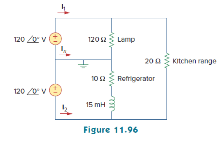
A regular household system of a single-phase three-wire circuit allows the operation of both 120-V and 240-V, 60-Hz appliances. The household circuit is modeled as shown in Fig. 11.96. Calculate:
- (a) the currents I1, I2, and In
- (b) the total complex power supplied
- (c) the overall power factor of the circuit
(a)
Find the currents
Explanation of Solution
Given data:
Refer to Figure 11.96 in the textbook.
The frequency
The circuits performs at both the voltages
The inductance L is
Formula used:
Write the expression for reactance of an inductor
Here,
L is the inductance.
Calculation:
Refer to Figure 11.96 in the textbook.
Substitute
The modified Figure is shown in Figure 1.
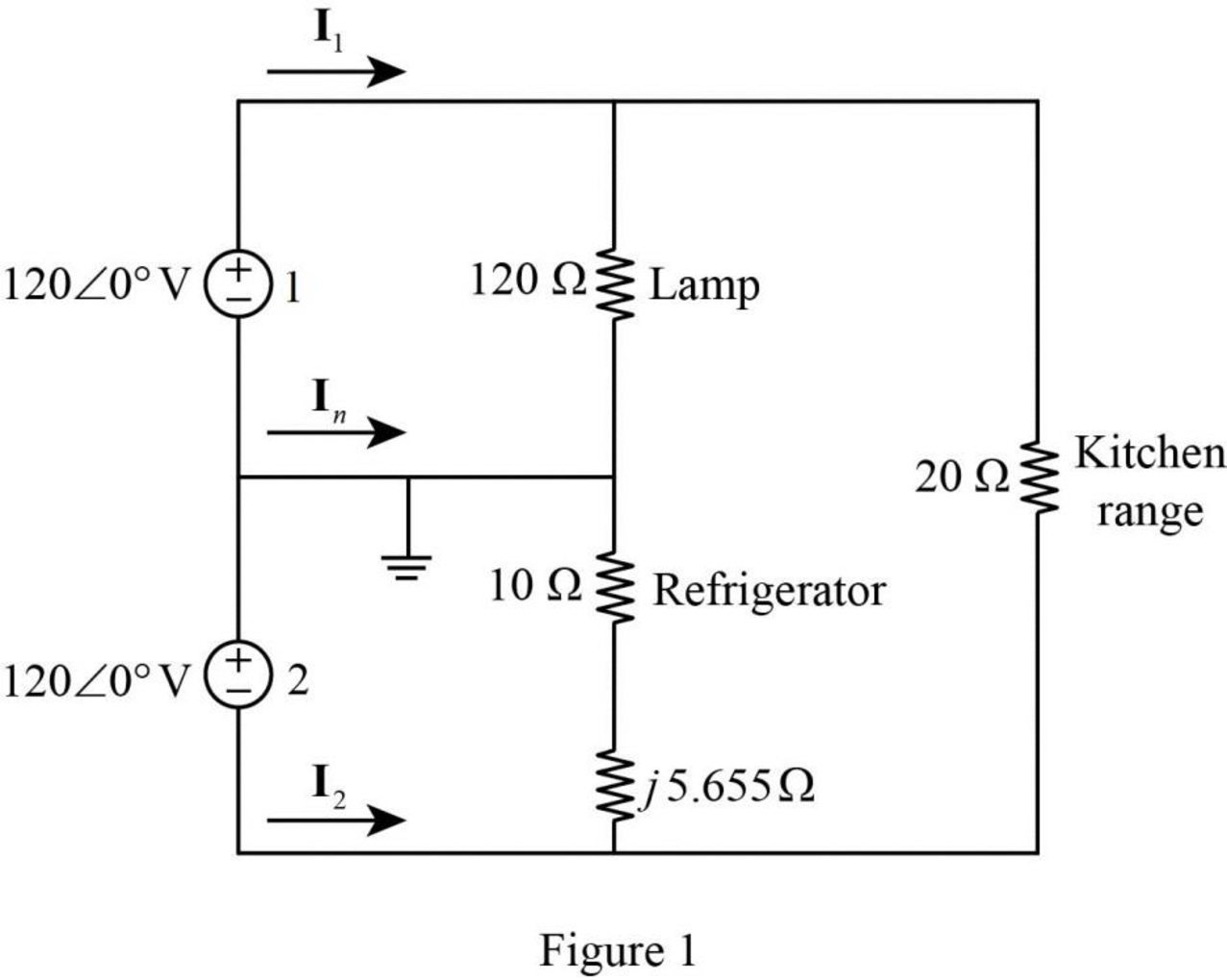
In Figure 1, the current flowing through the lamp
The current flowing through the refrigerator is calculated by using Ohm’s law as follows.
Convert the equation from polar to rectangular form.
The current flowing through the kitchen range
In Figure, apply Kirchhoff’s current law in the circuit. Therefore, the current
Similarly, the current
Convert the equation from rectangular to polar form.
Similarly, the current
Convert the equation from rectangular to polar form.
Conclusion:
Thus, the currents
(b)
Find the total complex power in the circuit of Figure 11.96.
Answer to Problem 85P
The total complex power is
Explanation of Solution
Given data:
Refer to Figure 11.96 in the textbook.
From part (a),
Calculation:
Refer to Figure 1 shown in Part (a).
The complex power delivered by the voltage source 1 is,
Substitute
The complex power delivered by voltage source 2 is,
Substitute
Simply the equation as follows,
Convert the equation from polar to rectangular form.
The total complex power is,
Substitute
Conclusion:
Thus, the total complex power is
(c)
Find the total power factor of the circuit shown in Figure 11.96.
Answer to Problem 85P
The total power factor of the circuit is 0.9888 (lagging).
Explanation of Solution
Given data:
Refer to Figure 11.96 in the textbook.
Formula used:
Write the expression for complex power.
Here,
P is the real power, and
Q is the reactive power.
Write the expression for power factor.
Calculation:
On comparing equation (2) and (3), the real power is,
From equation (2), the apparent power S is,
Substitute
Since,
Conclusion:
Thus, the total power factor of the circuit is 0.9888 (lagging).
Want to see more full solutions like this?
Chapter 11 Solutions
Fundamentals of Electric Circuits


- For the closed loop system shown in figure, determine the following:arrow_forwardWhat is the open loop transfer function and feedback for thia system? Determine the type of the open loop system. Find the poles s1 and s2 of the open loop system. If the input is a step function R(s)=1/s, find the step response c(t) of the open loop.arrow_forwardnot use ai please don'tarrow_forward
- 2. A DC generator is shown below. This DC generator is driven by a prime mover and rotating in counterclockwise direction. The armature is connected with a load resistor. (i) Using cross (x) or dot (*) to indicate the current direction of each conductor in the armature. (ii) If we want to reverse the polarity of the generated armature voltage, what can we do to? rotation S load Narrow_forward6. The figures below show the equivalent circuit of a separately excited DC generator and the approximate relationship between the flux of main field and exciting current. The field current I can be regulated by the variable resistor Ry, and the battery voltage supplying power to the exciter is 12V. The armature resistance Ro is 20, and the load is 182. For the DC generator, we aim to keep the voltage across the load (RL) constant in different speed range conditions. In the beginning, the flux is 0.12 Wb, the DC generator speed is 1000 rpm, and the generated voltage E。 is 100 V. Calculate: (1) The current flowing through the load. (2) When the speed of generator changes to 1500 rpm, how should we adjust the exciting current Ix to ensure Ę is still 100 V. (Hint: E₁ = Zno/60) (3) When the speed of generator changes to 500 rpm, how should we adjust the exciting current Ix to ensure Eo is still 100 V. (Hint: Eo = Zno/60) Rf ww (Wb) 0.17 0.15 12 V 1x F ele 1 1 2 ell Eo Ro ww 9 w RL Ix (A)arrow_forward7. For a shunt excited motor, the maximum allowable current is twice of the full-load current. The full-load current is 10 A. The equivalent circuit of this motor is also shown below. The rheostat can change the resistance by moving the slider (contact). The counter electromotive force (CEMF) for this motor is 100 V at 1000 rpm. The power supply E, is 200 V. In this case: (1) Calculate the minimum resistor value R at 0 rpm ensuing the motor is running within the safe range, and calculate the power consumed by the rheostat R. (2) Calculate the minimum effective resistor value R at 100 rpm ensuing the motor is running within the safe range, and calculate the power consumed by the rheostat R and the delivered mechanical power. (3) Calculate the minimum resistor value R at 500 rpm ensuing the motor is running within the safe range, and calculate the power consumed by the rheostat R the delivered mechanical power. shunt field R armature rheostat Es + Eoarrow_forward
- 4. For a general DC generator, we aim to achieve constant output voltage at different rotating speeds. (1) List two factors influencing the output voltage for a given DC generator. (2) How does the change of the load (assuming the load is the current flowing though the resistor) will impact on the generated voltage for (a) separately excited DC generator, (b) Shunt DC generator, and (c) cumulative compound DC generator?arrow_forward3. A DC motor is shown below. The armature is supplied by an external battery, and the current flowing direction of each conduction is depicted in the figure. (i) Draw the Lorentz force direction applied on each conductor in the armature. (ii) In which direction will the motor spin? What can we do to reverse the spinning direction? S Narrow_forward5. conditions. For a general DC motor, we aim to control the speed of the motor at different loading (1) List two factors influencing the motor speed for a given DC motor. (2) List three ways to stop a motor and comment on each method?arrow_forward
- Solve by Pen and Paper not using chatgptarrow_forwardf. The figure below shows two stage RC coupled amplifier. If the input resistance Rin of each stage is 1kN. (B = 100). Determine its overall voltage gain. (5 marks) +15V ΣΚΩ kn 10kΩ 10ΚΩ output 35 ΚΩ 2ΚΩ 5kЛ 2ΚΩarrow_forwardNO AI PLEASEarrow_forward
 Introductory Circuit Analysis (13th Edition)Electrical EngineeringISBN:9780133923605Author:Robert L. BoylestadPublisher:PEARSON
 Delmar's Standard Textbook Of ElectricityElectrical EngineeringISBN:9781337900348Author:Stephen L. HermanPublisher:Cengage Learning
 Programmable Logic ControllersElectrical EngineeringISBN:9780073373843Author:Frank D. PetruzellaPublisher:McGraw-Hill Education
 Fundamentals of Electric CircuitsElectrical EngineeringISBN:9780078028229Author:Charles K Alexander, Matthew SadikuPublisher:McGraw-Hill Education
 Electric Circuits. (11th Edition)Electrical EngineeringISBN:9780134746968Author:James W. Nilsson, Susan RiedelPublisher:PEARSON
 Engineering ElectromagneticsElectrical EngineeringISBN:9780078028151Author:Hayt, William H. (william Hart), Jr, BUCK, John A.Publisher:Mcgraw-hill Education,