
International Edition---engineering Mechanics: Statics, 4th Edition
4th Edition
ISBN: 9781305501607
Author: Andrew Pytel And Jaan Kiusalaas
Publisher: CENGAGE L
expand_more
expand_more
format_list_bulleted
Concept explainers
Videos
Textbook Question
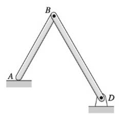
Chapter 10, Problem 10.20P
Locate the instant center of rotation of bar AB for each case shown.
Expert Solution & Answer
Want to see the full answer?
Check out a sample textbook solution
Students have asked these similar questions
In (Figure 1), take m₁ = 4 kg and mB = 4.6 kg.
Determine the z component of the angular momentum Ho of particle A about point O.
Determine the z component of the angular momentum Ho of particle B about point O. Suppose that
5 m
8 m/s
4 m
1.5 m
4 m
B
MB
1 m
2 m
5
30°
6 m/s
MA
The two disks A and B have a mass of 4 kg and 6 kg,
respectively. They collide with the initial velocities shown. The
coefficient of restitution is e = 0.75. Suppose that
(VA)1 = 6 m/s, (VB)₁ = 7 m/s. (Figure 1)
Determine the magnitude of the velocity of A just after impact.
Determine the angle between the x axis and the velocity of A just after impact, measured clockwise from the negative x axis.
Determine the magnitude of the velocity of B just after impact.
Determine the angle between the x axis and the velocity of B just after impact, measured clockwise from the positive x axis.
(VB)1
B
(VA)1
60°
Line of impact
A hot plane surface is maintained at 100°C, and it is exposed to air at 25°C.The combined heat transfer coefficient between the surface and the air is 25W/m²·K. (same as above). In this task, you are asked to design fins to cool asurface by attaching 3 cm-long, 0.25 cm-diameter aluminum pin fins (thermalconductivity, k = 237 W/m·K) with a center-to-center distance of 0.6 cm. (Tip:do not correct the length). Determine the rate of heat transfer from thefinned structure to the air for a 1 m x 1 m section of the plate.
Chapter 10 Solutions
International Edition---engineering Mechanics: Statics, 4th Edition
Ch. 10 - Determine the number of DOF for each of the...Ch. 10 - The uniform bar of weight W is held in equilibrium...Ch. 10 - Bars AB and AC of the mechanism are homogenous...Ch. 10 - The weight of each homogeneous bar of the linkage...Ch. 10 - The 1800-kg boat is suspended from two parallel...Ch. 10 - The 2.4-kg lamp, with center of gravity located at...Ch. 10 - The linkage is made of two homogenous bars of...Ch. 10 - For the frame shown, find the horizontal component...Ch. 10 - The four-bar linkage supports the homogeneous box...Ch. 10 - Prob. 10.10P
Ch. 10 - Determine the ratio P/Q of the forces that are...Ch. 10 - Find the vertical force P that will hold the...Ch. 10 - The linkage of the braking system consists of the...Ch. 10 - The automatic drilling robot must sustain a thrust...Ch. 10 - Determine the couple C for which the mechanism...Ch. 10 - The scissors jack is used to elevate the weight W....Ch. 10 - Prob. 10.17PCh. 10 - Calculate the torque C0 that must be applied to...Ch. 10 - Determine the force F and the angle a required to...Ch. 10 - Locate the instant center of rotation of bar AB...Ch. 10 - Prob. 10.21PCh. 10 - Determine the force P that will keep the mechanism...Ch. 10 - Prob. 10.23PCh. 10 - Prob. 10.24PCh. 10 - Prob. 10.25PCh. 10 - Determine the ratio P/Q for which the linkage will...Ch. 10 - Prob. 10.27PCh. 10 - Prob. 10.28PCh. 10 - If the input force to the compound lever is P = 30...Ch. 10 - Determine the roller reaction at F due to the...Ch. 10 - Prob. 10.31PCh. 10 - Prob. 10.32PCh. 10 - Prob. 10.33PCh. 10 - Prob. 10.34PCh. 10 - Prob. 10.35PCh. 10 - For the pliers shown, determine the relationship...Ch. 10 - When activated by the force P, the gripper cm a...Ch. 10 - Prob. 10.38PCh. 10 - The hinge is of the type used on some automobiles,...Ch. 10 - The spring attached to the sliding collar is...Ch. 10 - The weight W is suspended from end B of the...Ch. 10 - The uniform bar of weight W and length L = 1.8R...Ch. 10 - A slender homogeneous bar is bent into a right...Ch. 10 - The body shown is a composite of a hemisphere and...Ch. 10 - Prob. 10.45PCh. 10 - The uniform bar AB of weight W and length L is...Ch. 10 - Uniform rods of weights W1 and W2 are welded to...Ch. 10 - Prob. 10.48PCh. 10 - The semi-cylinder of radius r is placed on a...Ch. 10 - Prob. 10.50PCh. 10 - The spring attached to the homogenous bar of...Ch. 10 - The spring is connected to a rope that passes over...Ch. 10 - Find the equilibrium positions of the 30-lb...Ch. 10 - The mechanism of negligible weight supports the...Ch. 10 - Solve Prob. 10.54 assuming that A and B are...Ch. 10 - The stiffness of the ideal spring that is...Ch. 10 - Find the stable equilibrium position of the system...Ch. 10 - The uniform bar AB of weight W = kL is in...Ch. 10 - The weight of the uniform bar AB is W. The...Ch. 10 - The weightless bars AB and CE, together with the...Ch. 10 - Prob. 10.61PCh. 10 - The bar ABC is supported by three identical, ideal...
Knowledge Booster


Learn more about
Need a deep-dive on the concept behind this application? Look no further. Learn more about this topic, mechanical-engineering and related others by exploring similar questions and additional content below.Similar questions
- Heat is generated uniformly in a 4 cm-diameter, 16-cm long solid bar (k=2.4 W/m-K). The temperaturesat the center and at the surface of the bar are measured to be 210 oC and 45 oC, respectively. Calculatethe rate of heat generation within the bar. Solve the relevant energy balance equation and the boundaryconditions to calculate the rate of heat generation within the bar. (6 pts)arrow_forwardA hot plane surface is maintained at 100°C, and it is exposed to air at 25°C. The combined heat transfercoefficient between the surface and the air is 25 W/m²·K. You are tasked with designing an insulatingmaterial to cover the surface in order to reduce the heat transfer rate by 90%, meaning only 10% of theheat transfer would occur compared to the situation without insulation. The available insulating materialhas a thermal conductivity of 0.093 W/m·K. Assuming that the heat transfer coefficient and the surface/airtemperatures remain constant, calculate the required thickness of the insulating material in centimeters.arrow_forwardThe euler parameter in the image describes the orientation of N in the reference frame of U. How do I find the euler parameters that describe the orientation of U in the reference frame of N from the given information in the image.arrow_forward
- Fpull Ө A person, weighing 155 lb, is being lifted by a rope thrown. over a tree branch as shown (drawing not to scale). If the static coefficient of friction between the rope and the tree branch is us = 0.67, and the 0 = 45°. Determine the pulling force required to start lifting the person and the pulling force required to keep the person from falling? Pulling force to lift the person: Pulling force to keep the person from falling: lb lbarrow_forwardThe car weighs 1630 lbs and drives up the hill at a constant speed. Assuming the static friction coefficient between the wheels and the road is μs = 0.64, determine the steepest angle that the car can climb without slipping if it is.... a.) rear wheel drive b.) front wheel drive c.) four wheel drive a C CC ①⑧ BY NC Dr. Jacob Moore Values for dimensions on the figure are given in the following table. Note the figure may not be to scale. Variable Value a 8.75 ft b 3.325 ft C 1.66 ft a.) The steepest angle for rear wheel drive is 0 max degrees. b.) The steepest angle for front wheel drive is Omax degrees. c.) The steepest angle for four wheel drive is Omax degrees. = = =arrow_forwardFor the structure below, each member of the truss will safely support a tensile force of 3 kN and a compressive force of 1 kN. Determine the largest mass m that can be safely suspended. Hint: First work through this algebraically to find the forces in each member terms of the mass "m" to determine the largest stress member. 1 m t 1 m 1 m 1m + 1m E B 1977 marrow_forward
- Block A has a mass of 34 kg and block B has a mass of 41 kg. The two blocks are stacked on the ramp with an incline of Ꮎ 0 = 15.4°. Determine the largest horizontal force F that can be applied to block B without either block moving for each of the following two cases: a.) The friction coefficient for the contact between blocks A and B is μs1 0.56 and the friction coefficient for the = contact between block A and the ramp is μs2 = 0.34. b.) The friction coefficient for the contact between blocks A and B is 1 = 0.56 and the friction coefficient for the contact between block A and the ramp is μs2 = 0.17. Ꮎ F B A Part a) The limiting slip condition occurs at Select an answer CC BY NC SA 2016 Eric Davishahl The maximum force before either block A or B slips is N Part b) The limiting slip condition occurs at Select an answer The maximum force before either block A or B slips is Narrow_forwardThe crane truck has a weight of 11000 lb and a center of gravity at point . The parking brake only locks the rear wheels of the truck, so the front wheels are free to rotate. Determine the maximum force F applied at the angle = 0 30.5° that can be exerted on the crane without it slipping or tipping for each of the following cases: Case 1: The static friction coefficient between the rear tires and the ground is μ. = 0.050. ა Case 2: The static friction coefficient between the rear tires and the ground is μα == 0.33. d CGD 口 BY NC SA F 2013 Michael Swanbom кажо с Values for dimensions on the figure are given in the following table. Note the figure may not be to scale. Variable Value a 5.5 ft b 9 ft C 4 ft 3 ft 10 ft d h For Case 1, the constraint is Select an answer F = lbs. шал For Case 2, the constraint is Select an answer F пал lbs. and andarrow_forwardYou are leaning your 5.0 ft, 15.0 lb ladder against the wall in your garage. There are 2 rubber foot paddles on the bottom of the ladder, and your garage floor is concrete. The static friction between the rubber and concrete is μs = 0.580. What is the maximum distance from the wall to the rubber foot paddles, which you can lean your ladder without it slipping? Assume the wall is smooth. S The maximum distance = ftarrow_forward
- Instructions. "I have written solutions in text form, but I need experts to rewrite them in handwriting from A to Z, exactly as I have written, without any changes."arrow_forwardPearson eText Study Area mylabmastering.pearson.com Access Pearson P Pearson MyLab and Mastering Problem 14.78 P Course Home b Answered: HW_02.pdf EE 213-01 > Assignments HW_#... 2 of 8 Document Sharing User Settings The spring has a stiffness k = 200 N/m and an unstretched length of 0.5 m. It is attached to the 4.6-kg smooth collar and the collar is released from rest at A. Neglect the size of the collar. (Figure 1) Part A Determine the speed of the collar when it reaches B. Express your answer to three significant figures and include the appropriate units. Figure 1 of 1 με VB = Value Units Submit Request Answer Provide Feedback ? Review Next >arrow_forwardPearson eText Study Area Access Pearson mylabmastering.pearson.com P Pearson MyLab and Mastering Problem 15.79 P Course Home b Answered: HW_02.pdf EE 213-01 > Assignments HW_#... 6 of 8 > Document Sharing User Settings The two disks A and B have a mass of 4 kg and 5 kg, respectively. They collide with the initial velocities shown. The coefficient of restitution is e = 0.65. Suppose that (VA)1 = 6 m/s, (VB)1 = 8 m/s. (Figure 1) Part A Determine the magnitude of the velocity of A just after impact. Express your answer to three significant figures and include the appropriate units. Figure 1 of 1 μÅ (VA)2 = Value Units Submit Request Answer Part B ? Review Determine the angle between the x axis and the velocity of A just after impact, measured clockwise from the negative x axis. Express your answer in degrees to three significant figures. ΕΠΙ ΑΣΦ vec 01 Submit Request Answer Part C ? Determine the magnitude of the velocity of B just after impact. Express your answer to three significant…arrow_forward
arrow_back_ios
SEE MORE QUESTIONS
arrow_forward_ios
Recommended textbooks for you
 International Edition---engineering Mechanics: St...Mechanical EngineeringISBN:9781305501607Author:Andrew Pytel And Jaan KiusalaasPublisher:CENGAGE L
International Edition---engineering Mechanics: St...
Mechanical Engineering
ISBN:9781305501607
Author:Andrew Pytel And Jaan Kiusalaas
Publisher:CENGAGE L
Force | Free Body Diagrams | Physics | Don't Memorise; Author: Don't Memorise;https://www.youtube.com/watch?v=4Bwwq1munB0;License: Standard YouTube License, CC-BY