International Edition---engineering Mechanics: Statics, 4th Edition
4th Edition
ISBN: 9781305501607
Author: Andrew Pytel And Jaan Kiusalaas
Publisher: CENGAGE L
bartleby

Concept explainers

bartleby

Videos

Question
Book Icon
Chapter 10, Problem 10.31P
To determine

The couple C0 required to hold the mechanism in equilibrium.

Expert Solution & Answer
Check Mark

Answer to Problem 10.31P

The couple C0 required to hold the mechanism in equilibrium is 9.468Nm.

Explanation of Solution

Given:

For equilibrium the value of θ is 25°.

The value of force Q is 200 N.

Concept used:

To determine the couple C0, apply a virtual angular displacement at point A.

Draw the kinematic diagram for the mechanism as shown below:

  International Edition---engineering Mechanics: Statics, 4th Edition, Chapter 10, Problem 10.31P

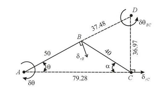
The instantaneous center of the system is at point D after theapplication of virtual angular displacement at point A the bar AB rotates about point A and bar BC will rotate about point D.

From above figure, by help of geometry angle α can be calculated as follows:

  sinα50=sinθ40sinα=50θ40

Simplify further for α.

  α=sin1(1.25θ) ...... (1)

Here, α is the angle made by link BC with horizontal and θ is the angle made by link AB with horizontal.

Write the expression for the distance between points A and C.

  dAC=50cosθ+40cosα......(2)

Here, dAC is the distance between the points A and C.

Write the expression for the distance between point C and D.

  dCD=dACtanθ......(3)

Here, dCD is the distance between the points C and D.

Write the expression for the distance between point A and D.

  dAD=dACcosθ......(4)

Here, dAD is the distance between the points A and D.

Write the expression for the distance between point B and D.

  dBD=dADdAB......(5)

Here, dBD is the distance between the points B and D.

Write the expression for displacement of point B fro bar AB.

  δrB=50δθ ...... (6)

Here, δrB is the displacement of point B and δθ is the virtual angular displacement at point A.

Write the expression for displacement of point B for bar BC.

  δrB=dBDδθBC ...... (7)

Here, δθBC is the angular displacement for bar BC about point D.

Write the expression for displacement of point C for bar BC.

  δrC=dCDδθBC ...... (8)

Here, δrC is the displacement of point C.

Write the expression for net virtual work done on the system.

  δU=C0δθQδrC ...... (9)

Here, δU is the net virtual work, C0 is the applied couple and Q is the applied force.

Calculation:

Substitute 25° for θ in equation (1).

  α=sin1(1.25( 25°))α=31.89°

Substitute 25° for θ and 31.89° for α in equation (2).

  dAC=50cos(25°)+40cos(31.89°)=79.28 mm

Substitute 25° for θ and 79.28mm for dAC in equation (3).

  dCD=79.28mm(tan25°)=36.97mm

Substitute 25° for θ and 79.28mm for dAC in equation (4).

  dAD=79.28 mmcos25°=87.48mm

Substitute 87.48mm for dAD and 50mm for dAB in equation (5).

  dBD=87.4850=37.48mm

Substitute 50δθ for δrB and 37.48mm for dBD in equation (7).

  50δθ=(37.48)δθBCδθBC=1.334δθ

Substitute 1.334δθ for δθBC and 36.97mm for dCD in equation (8).

  δrC=36.97(1.334δθ)=49.32δθ

Substitute 200 N for Q, 0 for δU and 49.32δθ for δrC in equation (9).

  0=C0δθ200(49.32δθ)0=(C09864)δθC0=9468Nmm( 1 m 1000 mm)C0=9.468Nm

The couple C0 required to hold the mechanism in equilibrium is 9.468Nm.

Conclusion:

Thus, the couple C0 required to hold the mechanism in equilibrium is 9.468Nm.

Want to see more full solutions like this?

Subscribe now to access step-by-step solutions to millions of textbook problems written by subject matter experts!
Students have asked these similar questions
2. Find the eigenvalues. Find the corresponding eigenvectors. 6 2 -21 [0 -3 1 3 31 a. 2 5 0 b. 3 0 -6 C. 1 1 0 -2 0 7 L6 6 0 1 1 2. (Hint: λ = = 3)
USE MATLAB ONLY provide typed code   solve for velocity triangle and dont provide copied answer  Turbomachienery .   GIven:  vx = 185 m/s, flow angle = 60 degrees, (leaving a stator in axial flow)  R = 0.5, U = 150 m/s, b2 = -a3, a2 = -b3   Find: velocity triangle , a. magnitude of abs vel leaving rotor (m/s) b. flow absolute angles (a1, a2, a3) 3. flow rel angles (b2, b3) d. specific work done e. use code to draw vel. diagram     Use this code for plot      % plots Velocity Tri. in Ch4 function plotveltri(al1,al2,al3,b2,b3)   S1L = [0 1]; V1x = [0 0]; V1s = [0 1*tand(al3)];   S2L = [2 3]; V2x = [0 0]; V2s = [0 1*tand(al2)]; W2s = [0 1*tand(b2)];   U2x = [3 3]; U2y = [1*tand(b2) 1*tand(al2)];   S3L = [4 5]; V3x = [0 0]; V3r = [0 1*tand(al3)]; W3r = [0 1*tand(b3)];   U3x = [5 5]; U3y = [1*tand(b3) 1*tand(al3)];   plot(S1L,V1x,'k',S1L,V1s,'r',... S2L,V2x,'k',S2L,V2s,'r',S2L,W2s,'b',U2x,U2y,'g',... S3L,V3x,'k',S3L,V3r,'r',S3L,W3r,'b',U3x,U3y,'g',...... 'LineWidth',2,'MarkerSize',10),...…
USE MATLAB ONLY provide typed code   solve for velocity triangle and dont provide copied answer  Turbomachienery .   GIven:  vx = 185 m/s, flow angle = 60 degrees, R = 0.5, U = 150 m/s, b2 = -a3, a2 = -b3   Find: velocity triangle , a. magnitude of abs vel leaving rotor (m/s) b. flow absolute angles (a1, a2, a3) 3. flow rel angles (b2, b3) d. specific work done e. use code to draw vel. diagram     Use this code for plot      % plots Velocity Tri. in Ch4 function plotveltri(al1,al2,al3,b2,b3)   S1L = [0 1]; V1x = [0 0]; V1s = [0 1*tand(al3)];   S2L = [2 3]; V2x = [0 0]; V2s = [0 1*tand(al2)]; W2s = [0 1*tand(b2)];   U2x = [3 3]; U2y = [1*tand(b2) 1*tand(al2)];   S3L = [4 5]; V3x = [0 0]; V3r = [0 1*tand(al3)]; W3r = [0 1*tand(b3)];   U3x = [5 5]; U3y = [1*tand(b3) 1*tand(al3)];   plot(S1L,V1x,'k',S1L,V1s,'r',... S2L,V2x,'k',S2L,V2s,'r',S2L,W2s,'b',U2x,U2y,'g',... S3L,V3x,'k',S3L,V3r,'r',S3L,W3r,'b',U3x,U3y,'g',...... 'LineWidth',2,'MarkerSize',10),... axis([-1 6 -4 4]), ...…

Chapter 10 Solutions

International Edition---engineering Mechanics: Statics, 4th Edition

Ch. 10 - Determine the ratio P/Q of the forces that are...Ch. 10 - Find the vertical force P that will hold the...Ch. 10 - The linkage of the braking system consists of the...Ch. 10 - The automatic drilling robot must sustain a thrust...Ch. 10 - Determine the couple C for which the mechanism...Ch. 10 - The scissors jack is used to elevate the weight W....Ch. 10 - Prob. 10.17PCh. 10 - Calculate the torque C0 that must be applied to...Ch. 10 - Determine the force F and the angle a required to...Ch. 10 - Locate the instant center of rotation of bar AB...Ch. 10 - Prob. 10.21PCh. 10 - Determine the force P that will keep the mechanism...Ch. 10 - Prob. 10.23PCh. 10 - Prob. 10.24PCh. 10 - Prob. 10.25PCh. 10 - Determine the ratio P/Q for which the linkage will...Ch. 10 - Prob. 10.27PCh. 10 - Prob. 10.28PCh. 10 - If the input force to the compound lever is P = 30...Ch. 10 - Determine the roller reaction at F due to the...Ch. 10 - Prob. 10.31PCh. 10 - Prob. 10.32PCh. 10 - Prob. 10.33PCh. 10 - Prob. 10.34PCh. 10 - Prob. 10.35PCh. 10 - For the pliers shown, determine the relationship...Ch. 10 - When activated by the force P, the gripper cm a...Ch. 10 - Prob. 10.38PCh. 10 - The hinge is of the type used on some automobiles,...Ch. 10 - The spring attached to the sliding collar is...Ch. 10 - The weight W is suspended from end B of the...Ch. 10 - The uniform bar of weight W and length L = 1.8R...Ch. 10 - A slender homogeneous bar is bent into a right...Ch. 10 - The body shown is a composite of a hemisphere and...Ch. 10 - Prob. 10.45PCh. 10 - The uniform bar AB of weight W and length L is...Ch. 10 - Uniform rods of weights W1 and W2 are welded to...Ch. 10 - Prob. 10.48PCh. 10 - The semi-cylinder of radius r is placed on a...Ch. 10 - Prob. 10.50PCh. 10 - The spring attached to the homogenous bar of...Ch. 10 - The spring is connected to a rope that passes over...Ch. 10 - Find the equilibrium positions of the 30-lb...Ch. 10 - The mechanism of negligible weight supports the...Ch. 10 - Solve Prob. 10.54 assuming that A and B are...Ch. 10 - The stiffness of the ideal spring that is...Ch. 10 - Find the stable equilibrium position of the system...Ch. 10 - The uniform bar AB of weight W = kL is in...Ch. 10 - The weight of the uniform bar AB is W. The...Ch. 10 - The weightless bars AB and CE, together with the...Ch. 10 - Prob. 10.61PCh. 10 - The bar ABC is supported by three identical, ideal...
Knowledge Booster
Background pattern image
Mechanical Engineering
Learn more about
Need a deep-dive on the concept behind this application? Look no further. Learn more about this topic, mechanical-engineering and related others by exploring similar questions and additional content below.
Similar questions
SEE MORE QUESTIONS
Recommended textbooks for you
Text book image
International Edition---engineering Mechanics: St...
Mechanical Engineering
ISBN:9781305501607
Author:Andrew Pytel And Jaan Kiusalaas
Publisher:CENGAGE L
Introduction to Undamped Free Vibration of SDOF (1/2) - Structural Dynamics; Author: structurefree;https://www.youtube.com/watch?v=BkgzEdDlU78;License: Standard Youtube License