Concept explainers
The angle
Answer to Problem 10.61P
The angle
Explanation of Solution
Given information:
Load
A diagram with all required dimensions has been given.
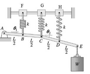
Calculation:
Consider the deflection of each spring is
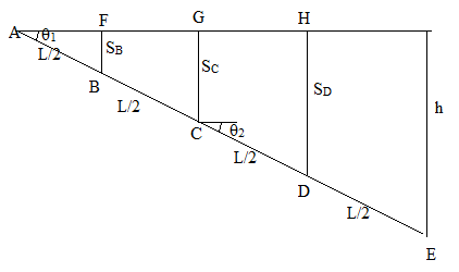
By using the geometry, deflection of each spring
The total potential energy = gravitational potential energy + potential energy of springs
Where,
Ve = Sum of potential energy of all springs
(Each value of potential energy of spring
Substituting, 2 and 3 in 1.
Now, differentiate V with respect to
Differentiating with respect to
Now, substituting
Similarly, differentiating with respect to
Now, substituting
Solving linear equations 4 and 5 simultaneously we get,
So taking inverse,
Want to see more full solutions like this?
Chapter 10 Solutions
International Edition---engineering Mechanics: Statics, 4th Edition
- The mass of the uniform bar ABis 40 kg. Calculate the couple Crequired for equilibrium if a.θ = 0 b.θ = 54°arrow_forwardThe jib crane is designed for a maximum capacity of 6 kN, and its uniform I-beam has a mass of 230 kg. Plot the magnitude R of the force on the pin at A as a function of x through its operating range of x = 0.2 m to x = 4.0 m. On the same set of axes, plot the x- and y- components of the pin reaction at A. Do these plots on a separate piece of paper. Then answer the following questions in Wiley Plus as a check for your work. (a) What is the value of R when x = 2.0 m? (b) What is the value of R when x = 3.3 m? (c) Determine the minimum value of R and the corresponding value of x. (d) For what value of R should the pin at A be designed? 34° x 1.3 m 6 kN -2.9 marrow_forwardConsider the following system in static equilibrium. Force vector Facts at a distance from the pin support at point O. Draw appropriate FBD as necessary. Assume frictionless pulleys If the reaction forces at O is zero and magnitude F is 169N, a. Find F and "a". (F need not necessarily be in the 4 quadrant as shown below) b. Find reaction forces at B. 4m Im 5m 12arrow_forward
- The jib crane is designed for a maximum capacity of 14 kN, and its uniform I-beam has a mass of 270 kg. Plot the magnitude R of the force on the pin at A as a function of x through its operating range of x = 0.2 m to x = 4.0 m. On the same set of axes, plot the x- and y-components of the pin reaction at A. Do these plots on a separate piece of paper. Then answer the following questions in Wiley Plus as a check for your work. (You can disregard the plot, I only need a, b, c, and d)arrow_forwardThe jib crane is designed for a maximum capacity of 14 kN, and its uniform I-beam has a mass of 270 kg. Plot the magnitude R of the force on the pin at A as a function of x through its operating range of x = 0.2 m to x = 4.9 m. On the same set of axes, plot the x- and y- components of the pin reaction at A. Do these plots on a separate piece of paper. Then answer the following questions in Wiley Plus as a check for your work. (a) What is the value of R when x = 2.4 m? (b) What is the value of R when x = 4.5 m? (c) Determine the minimum value of R and the corresponding value of x. (d) For what value of R should the pin at A be designed? 1.6 m Questions: 25° 14 KN -3.5 m (a) If x = 2.4 m, R = (b) If x= 4.5 m, R= (c) The minimum value for R = i (d) The pin should be designed to hold i KN KN kN at x = i kN. marrow_forwardProblem 2. Consider the frame loaded as shown. If the reaction force at the roller at F is 250N, then find the force P applied for equilibrium. 0.2 m 0.2 m 0.3 m E 60° |A |B 0.6 m 0.3 marrow_forward
- The jib crane is designed for a maximum capacity of 7 kN, and its uniform I-beam has a mass of 160 kg. Plot the magnitude R of the force on the pin at A as a function of x through its operating range of x = 0.2 m to x = 3.6 m. On the same set of axes, plot the x- and y-components of the pin reaction at A. Do these plots on a separate piece of paper. Then answer the following questions in Wiley Plus as a check for your work.(a) What is the value of R when x = 0.9 m?(b) What is the value of R when x = 3.1 m?(c) Determine the minimum value of R and the corresponding value of x.(d) For what value of R should the pin at A be designed?arrow_forwardThe jib crane is designed for a maximum capacity of 9 kN, and its uniform I-beam has a mass of 260 kg. Plot the magnitude R of the force on the pin at A as a function of x through its operating range of x = 0.2 m to x = 3.4 m. On the same set of axes, plot the x- and y- components of the pin reaction at A. Do these plots on a separate piece of paper. Then answer the following questions in Wiley Plus as a check for your work. (a) What is the value of R when x = 1.6 m? (b) What is the value of R when x = 3.2 m? (c) Determine the minimum value of R and the corresponding value of x. (d) For what value of R should the pin at A be designed? 32° x m 9 KN 1.0 m 2.6 m Questions: (a) If x= 1.6 m, R= i (b) If x= 3.2 m, R = i (c) The minimum value for R = i (d) The pin should be designed to hold i KN KN kN at x = i kN.arrow_forwardThe jib crane is designed for a maximum capacity of 5 kN, and its uniform I-beam has a mass of 200 kg. Plot the magnitude R of the force on the pin at A as a function of x through its operating range of x = 0.2 m to x = 3.9 m. On the same set of axes, plot the x- and y- components of the pin reaction at A. Do these plots on a separate piece of paper. Then answer the following questions in Wiley Plus as a check for your work. (a) What is the value of R when x = 0.8 m? (b) What is the value of R when x = 3.2 m? (c) Determine the minimum value of R and the corresponding value of x. (d) For what value of R should the pin at A be designed? 40° m 5 KN -2.9 m 1.2 m Questions: (a) If x = 0.8 m, R= (b) If x= 3.2 m, R= i (c) The minimum value for R = i (d) The pin should be designed to hold i kN kN kN at x = kN.arrow_forward
- 1 ft 4 ft A 2 ft 45° X 5 B 3 ft Z 45° F₂ 5 ft 30° If F₁ = 300 lb. and F₂ is 250 lb., what are the reaction components on the smooth journal bearings A,B and C? Include a free body diagram of the bent pipe. F₁ lies entirely in the y-z plane.arrow_forwardThe weight of the limb is W=15 lbs.The contact of foot with the ground can be modeled as a pin/hinge here. Determine the reaction force of the ground and the reaction at the knee joint and its direction/angle θ. Note: use the thee force member condition to find the angle of FK.Q4.As it’s been shown in the below figure,a person is using an exercise machine. Points A and B correspond to the shoulder and elbow joints, respectively. Relative to the person, the upper arm (AB) is extended toward the left (x-direction) and the lower arm (BC) is extended forward (z-direction). At this instant, the person is holding a handle that is connected by a cable to a suspending weight. The weight applies an upward (in the y-direction) force with magnitude F on the arm at point C. The lengths of the upper arm and lower arm are AB̅̅̅̅= 20cm and BC̅̅̅̅= 25cm, respectively, and the magnitude of the applied force is F = 400 N.Determine the components of reaction developed at the shoulder joint A When the…arrow_forwardh A B Farrow_forward
- International Edition---engineering Mechanics: St...Mechanical EngineeringISBN:9781305501607Author:Andrew Pytel And Jaan KiusalaasPublisher:CENGAGE L