
Theory and Design for Mechanical Measurements
6th Edition
ISBN: 9781118881279
Author: Richard S. Figliola, Donald E. Beasley
Publisher: WILEY
expand_more
expand_more
format_list_bulleted
Videos
Textbook Question
Chapter 1, Problem 1.25P
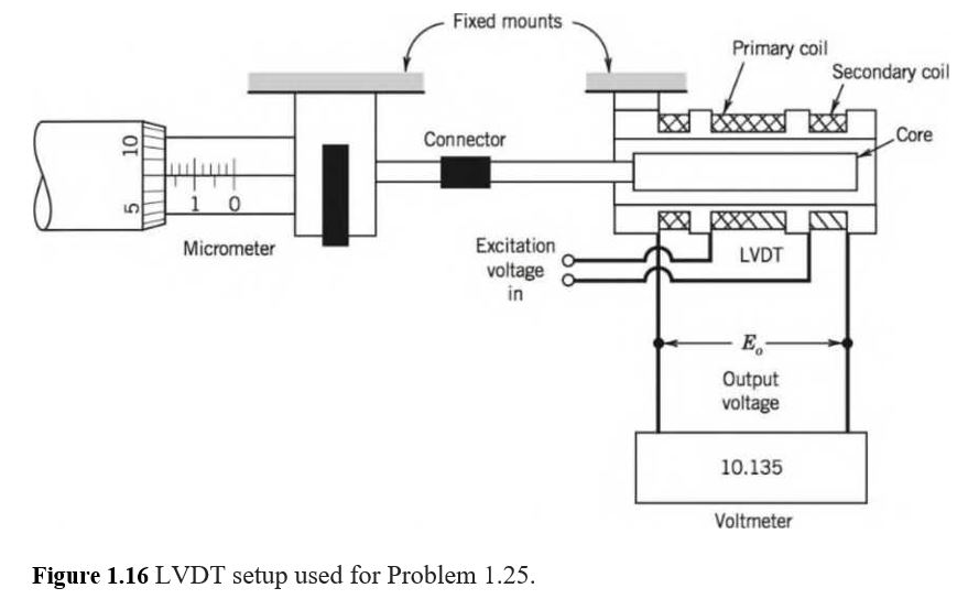
1.25 A linear variable displacement transducer (LVDT) senses displacement and indicates a voltage output that is linear to the input. Figure 1.16 shows an LVDT setup used for static calibration. It uses a micrometer to apply the known displacement and a voltmeter for the output. A well-defined voltage powers the transducer. What are the independent and dependent variables in this calibration? Would these change in practical use?
Expert Solution & Answer
Want to see the full answer?
Check out a sample textbook solution
Students have asked these similar questions
Qu 5 Determine the carburizing time necessary to achieve a carbon concentration of 0.30 wt% at a position 4 mm into an iron carbon alloy that initially contains 0.10 wt% C. The surface concentration is to be maintained at 0.90 wt% C, and the treatment is to be conducted at 1100°C. Use the data for the diffusion of
carbon into y-iron: Do = 2.3 x10⁻⁵ m2/s and Qd = 148,000 J/mol. Express your answer in hours to three significant figures.
show all work step by step problems formula material science
(Read Question)
In figure A, the homogeneous rod of constant cross section is attached to unyielding supports. In figure B, a homogeneous bar with a cross-sectional area of 600 mm2 is attached to rigid supports. The bar carries the axial loads P1 = 20 kN and P2 = 60 kN, as shown.1. In figure A, derive the expression that calculates the reaction R1 in terms of P, and the given dimensions.2. In figure B, calculate the reaction (kN) at A.3. In figure B, calculate the maximum axial stress (MPa) in the rod.
Chapter 1 Solutions
Theory and Design for Mechanical Measurements
Ch. 1 - Prob. 1.1PCh. 1 - Prob. 1.2PCh. 1 - Prob. 1.3PCh. 1 - Prob. 1.4PCh. 1 - Prob. 1.5PCh. 1 - Discuss how the resolution of the display scale of...Ch. 1 - Prob. 1.7PCh. 1 - Prob. 1.8PCh. 1 - Prob. 1.9PCh. 1 - Prob. 1.10P
Ch. 1 - State the purpose of using randomization methods...Ch. 1 - Provide an example of repetition and replication...Ch. 1 - Develop a test plan that might be used to estimate...Ch. 1 - Develop a test plan that might be used to evaluate...Ch. 1 - A race engine shop has just completed two engines...Ch. 1 - A thermodynamics model assumes that a particular...Ch. 1 - Regarding the Mars Climate Orbiter spacecraft...Ch. 1 - A large batch of carefully made machine shafts can...Ch. 1 - Suggest an approach or approaches to estimate the...Ch. 1 - Suggest a test matrix to evaluate the wear...Ch. 1 - Figure 1.15 Orifice flow meter setup used for...Ch. 1 - The sale of motor fuel is an essential business in...Ch. 1 - Using either the ASME 19.5 or ISO 5167 test...Ch. 1 - A simple thermocouple circuit is formed using two...Ch. 1 - 1.25 A linear variable displacement transducer...Ch. 1 - For the LVDT calibration of the previous problem,...Ch. 1 - A manufacturer wants to quantify the expected...Ch. 1 - Prob. 1.28PCh. 1 - As described in a preceding problem, the...Ch. 1 - Light gates may be used to measure the speed of...Ch. 1 - You estimate your car’s fuel use by recording...Ch. 1 - When discussing concomitant methods, we used the...Ch. 1 - Prob. 1.33PCh. 1 - For the strain gauge calibration of the previous...Ch. 1 - The acceleration of a cart down a plane inclined...Ch. 1 - In general, what is meant by the term “standard”?...Ch. 1 - A common scenario: An engineer has two pencil-...Ch. 1 - Explain the potential differences in the following...Ch. 1 - Research the following test standards and codes....Ch. 1 - A hotel chain based in the United States contracts...Ch. 1 - Test code ASTM 558-13 allows for the comparison of...Ch. 1 - Suggest a reasonable number of significant digits...Ch. 1 - Using spreadsheet software (such as Microsoft...Ch. 1 - Prob. 1.44PCh. 1 - Round the following numbers to 3 significant...Ch. 1 - Express the result, rounding to an appropriate num...Ch. 1 - Express the result by rounding to an appropriate...Ch. 1 - A car’s speed is determined by the time it takes...Ch. 1 - How much error could you tolerate in (1) book...Ch. 1 - Apply the guidelines to determine the number of...Ch. 1 - Using a tape measure having 1 mm graduations, the...Ch. 1 - Show how the following functions can be...Ch. 1 - Prob. 1.53PCh. 1 - For the calibration data of Table 1.5, determine...Ch. 1 - Prob. 1.55PCh. 1 - Each of the following equations can be represented...Ch. 1 - Plot y = 10e“° 5x volts on in semilog format (use...Ch. 1 - Prob. 1.58PCh. 1 - Prob. 1.59P
Knowledge Booster


Learn more about
Need a deep-dive on the concept behind this application? Look no further. Learn more about this topic, mechanical-engineering and related others by exploring similar questions and additional content below.Similar questions
- (Read image)arrow_forward(Read Image)arrow_forwardM16x2 grade 8.8 bolts No. 25 C1- Q.2. The figure is a cross section of a grade 25 cast-iron pressure vessel. A total of N, M16x2.0 grade 8.8 bolts are to be used to resist a separating force of 160 kN. (a) Determine ks, km, and C. (b) Find the number of bolts required for a load factor of 2 where the bolts may be reused when the joint 19 mm is taken apart. (c) with the number of bolts obtained in (b), determine the realized load factor for overload, the yielding factor of safety, and the separation factor of safety. 19 mmarrow_forward
- Problem4. The thin uniform disk of mass m = 1-kg and radius R = 0.1m spins about the bent shaft OG with the angular speed w2 = 20 rad/s. At the same time, the shaft rotates about the z-axis with the angular speed 001 = 10 rad/s. The angle between the bent portion of the shaft and the z-axis is ẞ = 35°. The mass of the shaft is negligible compared to the mass of the disk. a. Find the angular momentum of the disk with respect to point G, based on the axis orientation as shown. Include an MVD in your solution. b. Find the angular momentum of the disk with respect to point O, based on the axis orientation as shown. (Note: O is NOT the center of fixed-point rotation.) c. Find the kinetic energy of the assembly. z R R 002 2R x Answer: H = -0.046ĵ-0.040 kg-m²/sec Ho=-0.146-0.015 kg-m²/sec T 0.518 N-m =arrow_forwardProblem 3. The assembly shown consists of a solid sphere of mass m and the uniform slender rod of the same mass, both of which are welded to the shaft. The assembly is rotating with angular velocity w at a particular moment. Find the angular momentum with respect to point O, in terms of the axes shown. Answer: Ñ。 = ½mc²wcosßsinßĵ + (}{mr²w + 2mb²w + ½ mc²wcos²ß) k 3 m r b 2 C لا marrow_forwardOnly question 2arrow_forward
- Only question 1arrow_forwardOnly question 3arrow_forwardI have Euler parameters that describe the orientation of N relative to Q, e = -0.7071*n3, e4 = 0.7071. I have Euler parameters that describe the orientation of U relative to N, e = -1/sqrt(3)*n1, e4 = sqrt(2/3). After using euler parameter rule of successive rotations, I get euler parameters that describe the orientation of U relative to Q, e = -0.4082*n1 - 0.4082*n2 - 0.5774*n3. I need euler parameters that describe the orientation of U relative to Q in vector basis of q instead of n. How do I get that?arrow_forward
- Describe at least 4 processes in engineering where control charts are (or should be) appliedarrow_forwardDescribe at least two (2) processes where control charts are (or should be) applied.arrow_forwardProblem 3: A cube-shaped spacecraft is in a circular Earth orbit. Let N (n,) be inertial and the spacecraft is denoted S (ŝ₁). The spacecraft is described such that ¯½º = J ŝ₁ŝ₁ + J ŝ₂§₂ + J §¸Ŝ3 Location of the spacecraft in the orbit is determined by the orbit-fixed unit vectors ê, that are oriented by the angle (Qt), where is a constant angular rate. 52 €3 3> 2t 55 Λ Из At the instant when Qt = 90°, the spacecraft S is oriented relative to the orbit such that 8₁ = 0° Space-three 1-2-3 angles 0₂ = 60° and ES = $₂ rad/s 0₁ = 135° (a) At this instant, determine the direction cosine matrix that describes the orientation of the spacecraft with respect to the inertial frame N.arrow_forward
arrow_back_ios
SEE MORE QUESTIONS
arrow_forward_ios
Recommended textbooks for you
 Elements Of ElectromagneticsMechanical EngineeringISBN:9780190698614Author:Sadiku, Matthew N. O.Publisher:Oxford University Press
 Mechanics of Materials (10th Edition)Mechanical EngineeringISBN:9780134319650Author:Russell C. HibbelerPublisher:PEARSON
 Thermodynamics: An Engineering ApproachMechanical EngineeringISBN:9781259822674Author:Yunus A. Cengel Dr., Michael A. BolesPublisher:McGraw-Hill Education
 Control Systems EngineeringMechanical EngineeringISBN:9781118170519Author:Norman S. NisePublisher:WILEY
 Mechanics of Materials (MindTap Course List)Mechanical EngineeringISBN:9781337093347Author:Barry J. Goodno, James M. GerePublisher:Cengage Learning
 Engineering Mechanics: StaticsMechanical EngineeringISBN:9781118807330Author:James L. Meriam, L. G. Kraige, J. N. BoltonPublisher:WILEY
Elements Of Electromagnetics
Mechanical Engineering
ISBN:9780190698614
Author:Sadiku, Matthew N. O.
Publisher:Oxford University Press
Mechanics of Materials (10th Edition)
Mechanical Engineering
ISBN:9780134319650
Author:Russell C. Hibbeler
Publisher:PEARSON
Thermodynamics: An Engineering Approach
Mechanical Engineering
ISBN:9781259822674
Author:Yunus A. Cengel Dr., Michael A. Boles
Publisher:McGraw-Hill Education
Control Systems Engineering
Mechanical Engineering
ISBN:9781118170519
Author:Norman S. Nise
Publisher:WILEY
Mechanics of Materials (MindTap Course List)
Mechanical Engineering
ISBN:9781337093347
Author:Barry J. Goodno, James M. Gere
Publisher:Cengage Learning
Engineering Mechanics: Statics
Mechanical Engineering
ISBN:9781118807330
Author:James L. Meriam, L. G. Kraige, J. N. Bolton
Publisher:WILEY
Dimensional Analysis - in physics; Author: Jennifer Cash;https://www.youtube.com/watch?v=c_ZUnEUlTbM;License: Standard youtube license