
Theory and Design for Mechanical Measurements
6th Edition
ISBN: 9781118881279
Author: Richard S. Figliola, Donald E. Beasley
Publisher: WILEY
expand_more
expand_more
format_list_bulleted
Concept explainers
Videos
Textbook Question
Chapter 1, Problem 1.21P
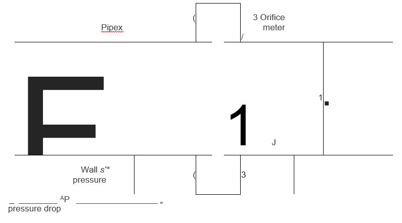
Figure 1.15 Orifice flow meter setup used for Problem 1.21.
1.21 The relation between the flow rate, Q, through a pipeline of area A and the pressure drop Ap across an orifice-type flow meter inserted in that line (Figure 1.15) is given by Q = CAyJlApIp where p is density and C is a coefficient. For a pipe diameter of 1 m and a flow range of 20 °C water between 2
•J
and 10 m /min and C = 0.75, plot the expected form of the calibration curve for flow rate versus pressure drop over the flow range. Is the static sensitivity a constant? Incidentally, the device and test method is described by both ANSI/ASME Test Standard PTC 19.5 and ISO 5167.
Expert Solution & Answer
Want to see the full answer?
Check out a sample textbook solution
Students have asked these similar questions
2.
3.
4.
clockwise from
Four masses A, B, C and D revolve at equal radii and are equally spaced along a shaft. The mass B
is 7 kg and the radii of C and D make angles of 90° and 240° respectively with the radius of B. Find
the magnitude of the masses A, C and D and the angular position of A so that the system may be
completely balanced.
[Ans. 5 kg: 6 kg; 4.67 kg; 205° from mass B in anticlockwise direction]
A rotating shaft carries four masses A, B, C and D which are radially attached to it. The mass
centres are 30 mm, 38 mm, 40 mm and 35 mm respectively from the axis of rotation. The masses
A, C and D are 7.5 kg. 5 kg and 4 kg respectively. The axial distances between the planes of
rotation of A and B is 400 mm and between B and C is 500 mm. The masses A and C are at right
angles to each other. Find for a complete balance,
1. the angles between the masses B and D from mass A,
2. the axial distance between the planes of rotation of C and D.
3. the magnitude of mass B.
[Ans. 162.5%,…
1. Four masses A, B, C and D are attached to a shaft and revolve in the same plane. The masses are 12
kg. 10 kg. 18 kg and 15 kg respectively and their radii of rotations are 40 mm, 50 mm, 60 mm and
30 mm. The angular position of the masses B, C and D are 60°, 135° and 270 from the mass A.
Find the magnitude and position of the balancing mass at a radius of 100 mm.
[Ans. 7.56 kg: 87 clockwise from A]
3. The structure in Figure 3 is loaded by a horizontal force P = 2.4 kN at C. The roller at E is
frictionless. Find the axial force N, the shear force V and the bending moment M at a section
just above the pin B in the member ABC and illustrate their directions on a sketch of the segment
AB.
B
P
D
A
65°
65°
E
all dimensions in meters
Figure 3
Chapter 1 Solutions
Theory and Design for Mechanical Measurements
Ch. 1 - Prob. 1.1PCh. 1 - Prob. 1.2PCh. 1 - Prob. 1.3PCh. 1 - Prob. 1.4PCh. 1 - Prob. 1.5PCh. 1 - Discuss how the resolution of the display scale of...Ch. 1 - Prob. 1.7PCh. 1 - Prob. 1.8PCh. 1 - Prob. 1.9PCh. 1 - Prob. 1.10P
Ch. 1 - State the purpose of using randomization methods...Ch. 1 - Provide an example of repetition and replication...Ch. 1 - Develop a test plan that might be used to estimate...Ch. 1 - Develop a test plan that might be used to evaluate...Ch. 1 - A race engine shop has just completed two engines...Ch. 1 - A thermodynamics model assumes that a particular...Ch. 1 - Regarding the Mars Climate Orbiter spacecraft...Ch. 1 - A large batch of carefully made machine shafts can...Ch. 1 - Suggest an approach or approaches to estimate the...Ch. 1 - Suggest a test matrix to evaluate the wear...Ch. 1 - Figure 1.15 Orifice flow meter setup used for...Ch. 1 - The sale of motor fuel is an essential business in...Ch. 1 - Using either the ASME 19.5 or ISO 5167 test...Ch. 1 - A simple thermocouple circuit is formed using two...Ch. 1 - 1.25 A linear variable displacement transducer...Ch. 1 - For the LVDT calibration of the previous problem,...Ch. 1 - A manufacturer wants to quantify the expected...Ch. 1 - Prob. 1.28PCh. 1 - As described in a preceding problem, the...Ch. 1 - Light gates may be used to measure the speed of...Ch. 1 - You estimate your car’s fuel use by recording...Ch. 1 - When discussing concomitant methods, we used the...Ch. 1 - Prob. 1.33PCh. 1 - For the strain gauge calibration of the previous...Ch. 1 - The acceleration of a cart down a plane inclined...Ch. 1 - In general, what is meant by the term “standard”?...Ch. 1 - A common scenario: An engineer has two pencil-...Ch. 1 - Explain the potential differences in the following...Ch. 1 - Research the following test standards and codes....Ch. 1 - A hotel chain based in the United States contracts...Ch. 1 - Test code ASTM 558-13 allows for the comparison of...Ch. 1 - Suggest a reasonable number of significant digits...Ch. 1 - Using spreadsheet software (such as Microsoft...Ch. 1 - Prob. 1.44PCh. 1 - Round the following numbers to 3 significant...Ch. 1 - Express the result, rounding to an appropriate num...Ch. 1 - Express the result by rounding to an appropriate...Ch. 1 - A car’s speed is determined by the time it takes...Ch. 1 - How much error could you tolerate in (1) book...Ch. 1 - Apply the guidelines to determine the number of...Ch. 1 - Using a tape measure having 1 mm graduations, the...Ch. 1 - Show how the following functions can be...Ch. 1 - Prob. 1.53PCh. 1 - For the calibration data of Table 1.5, determine...Ch. 1 - Prob. 1.55PCh. 1 - Each of the following equations can be represented...Ch. 1 - Plot y = 10e“° 5x volts on in semilog format (use...Ch. 1 - Prob. 1.58PCh. 1 - Prob. 1.59P
Knowledge Booster


Learn more about
Need a deep-dive on the concept behind this application? Look no further. Learn more about this topic, mechanical-engineering and related others by exploring similar questions and additional content below.Similar questions
- 4. The distributed load in Figure 4 varies linearly from 3wo per unit length at A to wo per unit length at B and the beam is built in at A. Find expressions for the shear force V and the bending moment M as functions of x. 3W0 Wo A L Figure 4 2 Barrow_forward1. The beam AB in Figure 1 is subjected to a uniformly distributed load wo = 100 N/m. Find the axial force N, the shear force V and the bending moment M at the point D which is midway between A and B and illustrate their directions on a sketch of the segment DB. wo per unit length A D' B all dimensions in metersarrow_forward5. Find the shear force V and the bending moment M for the beam of Figure 5 as functions of the distance x from A. Hence find the location and magnitude of the maximum bending moment. w(x) = wox L x L Figure 5 Barrow_forward
- Dry atmospheric air enters an adiabatic compressor at a 20°C, 1 atm and a mass flow rate of 0.3kg/s. The air is compressed to 1 MPa. The exhaust temperature of the air is 70 degrees hottercompared to the exhaust of an isentropic compression.Determine,a. The exhaust temperature of the air (°C)b. The volumetric flow rate (L/s) at the inlet and exhaust of the compressorc. The power required to accomplish the compression (kW)d. The isentropic efficiency of the compressore. An accounting of the exergy entering the compressor (complete Table P3.9) assuming that thedead state is the same as State 1 (dry atmospheric air)f. The exergetic efficiency of the compressorarrow_forwardA heat pump is operating between a low temperature reservoir of 270 K and a high temperaturereservoir of 340 K. The heat pump receives heat at 255 K from the low temperature reservoir andrejects heat at 355 K to the high temperature reservoir. The heating coefficient of performance ofthe heat pump is 3.2. The heat transfer rate from the low temperature reservoir is 30 kW. The deadstate temperature is 270 K. Determine,a. Power input to the heat pump (kW)b. Heat transfer rate to the high-temperature reservoir (kW)c. Exergy destruction rate associated with the low temperature heat transfer (kW)d. Exergy destruction rate of the heat pump (kW)e. Exergy destruction rate associated with the high temperature heat transfer (kW)f. Exergetic efficiency of the heat pump itselfarrow_forwardRefrigerant 134a (Table B6, p514 of textbook) enters a tube in the evaporator of a refrigerationsystem at 132.73 kPa and a quality of 0.15 at a velocity of 0.5 m/s. The R134a exits the tube as asaturated vapor at −21°C. The tube has an inside diameter of 3.88 cm. Determine the following,a. The pressure drop of the R134a as it flows through the tube (kPa)b. The volumetric flow rate at the inlet of the tube (L/s)c. The mass flow rate of the refrigerant through the tube (g/s)d. The volumetric flow rate at the exit of the tube (L/s)e. The velocity of the refrigerant at the exit of the tube (m/s)f. The heat transfer rate to the refrigerant (kW) as it flows through the tubearrow_forward
- Water enters the rigid, covered tank shown in Figure P3.2 with a volumetric flow rate of 0.32L/s. The water line has an inside diameter of 6.3 cm. The air vent on the tank has an inside diameterof 4.5 cm. The water is at a temperature of 30°C and the air in the tank is at atmospheric pressure(1 atm) and 30°C. Determine the air velocity leaving the vent at the instant shown in the figurearrow_forwardUsing method of sections, determine the force in member BC, HC, and HG. State if these members are in tension or compression. 2 kN A 5 kN 4 kN 4 kN 3 kN H B C D E 3 m F 2 m -5 m 5 m- G 5 m 5 m-arrow_forwardDetermine the normal stresses σn and σt and the shear stress τnt at this point if they act on the rotated stress element shownarrow_forward
- Using method of joints, determine the force in each member of the truss and state if the members are in tension or compression. A E 6 m D 600 N 4 m B 4 m 900 Narrow_forwardQuestion 5. The diagram below shows a mass suspended from a tie supported by two horizontal braces of equal length. The tie forms an angle "a" of 60° to the horizontal plane, the braces form an angle 0 of 50° to the vertical plane. If the mass suspended is 10 tonnes, and the braces are 10m long, find: a) the force in the tie; & b) the force in the braces Horizontal Braces, Tie Massarrow_forward= MMB 241 Tutorial 2.pdf 1 / 3 75% + + Tutorial z Topic: Kinematics of Particles:-. QUESTIONS 1. Use the chain-rule and find y and ŷ in terms of x, x and x if a) y=4x² b) y=3e c) y = 6 sin x 2. The particle travels from A to B. Identify the three unknowns, and write the three equations needed to solve for them. 8 m 10 m/s 30° B x 3. The particle travels from A to B. Identify the three unknowns, and write the three equations needed to solve for them. A 40 m/s 20 m B 1arrow_forward
arrow_back_ios
SEE MORE QUESTIONS
arrow_forward_ios
Recommended textbooks for you
 Elements Of ElectromagneticsMechanical EngineeringISBN:9780190698614Author:Sadiku, Matthew N. O.Publisher:Oxford University Press
 Mechanics of Materials (10th Edition)Mechanical EngineeringISBN:9780134319650Author:Russell C. HibbelerPublisher:PEARSON
 Thermodynamics: An Engineering ApproachMechanical EngineeringISBN:9781259822674Author:Yunus A. Cengel Dr., Michael A. BolesPublisher:McGraw-Hill Education
 Control Systems EngineeringMechanical EngineeringISBN:9781118170519Author:Norman S. NisePublisher:WILEY
 Mechanics of Materials (MindTap Course List)Mechanical EngineeringISBN:9781337093347Author:Barry J. Goodno, James M. GerePublisher:Cengage Learning
 Engineering Mechanics: StaticsMechanical EngineeringISBN:9781118807330Author:James L. Meriam, L. G. Kraige, J. N. BoltonPublisher:WILEY
Elements Of Electromagnetics
Mechanical Engineering
ISBN:9780190698614
Author:Sadiku, Matthew N. O.
Publisher:Oxford University Press
Mechanics of Materials (10th Edition)
Mechanical Engineering
ISBN:9780134319650
Author:Russell C. Hibbeler
Publisher:PEARSON
Thermodynamics: An Engineering Approach
Mechanical Engineering
ISBN:9781259822674
Author:Yunus A. Cengel Dr., Michael A. Boles
Publisher:McGraw-Hill Education
Control Systems Engineering
Mechanical Engineering
ISBN:9781118170519
Author:Norman S. Nise
Publisher:WILEY
Mechanics of Materials (MindTap Course List)
Mechanical Engineering
ISBN:9781337093347
Author:Barry J. Goodno, James M. Gere
Publisher:Cengage Learning
Engineering Mechanics: Statics
Mechanical Engineering
ISBN:9781118807330
Author:James L. Meriam, L. G. Kraige, J. N. Bolton
Publisher:WILEY
8.01x - Lect 27 - Fluid Mechanics, Hydrostatics, Pascal's Principle, Atmosph. Pressure; Author: Lectures by Walter Lewin. They will make you ♥ Physics.;https://www.youtube.com/watch?v=O_HQklhIlwQ;License: Standard YouTube License, CC-BY
Dynamics of Fluid Flow - Introduction; Author: Tutorials Point (India) Ltd.;https://www.youtube.com/watch?v=djx9jlkYAt4;License: Standard Youtube License