
Concept explainers
Videos
Two cover plates are welded to the rolled-steel beam as shown. Using E = 200 GPa, determine (a) the slope at end A, (b) the deflection at end A. 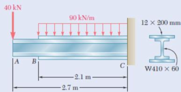
Fig. P9.107
(a)
Find the slope
Answer to Problem 107P
The slope
Explanation of Solution
Given information:
The elastic modulus (E) is
The section of the beam is
The dimension of the top plate and bottom plate is
Calculation:
Refer Appendix C, “Properties of Rolled steel shapes”.
The moment of inertia (I) for the given section is
The depth of the section (D) is
The width of the section (b) is
Use moment area method:
Consider from bottom.
Calculate the neutral axis
Substitute
Top plate:
Calculate the area of the top plate
Since the dimension of the top plate is
Calculate the depth of neutral axis (d) using the formula:
Substitute
Calculate the product of
Substitute
Calculate the moment of inertia (I) using the formula:
Here, b is the width the top plate and h is the height of the top plate.
Substitute 200 mm for b and 12 mm for h.
Bottom plate:
Top plate:
Calculate the area of the bottom plate
Since the dimension of the bottom plate is
Calculate the depth of neutral axis (d) using the formula:
Substitute
Calculate the product of
Substitute
Calculate the moment of inertia (I) using the formula:
Here, b is the width the top plate and h is the height of the top plate.
Substitute
Tabulate the calculated values and compute the moment of inertia (I) as in Table 1.
| Segments | Area, A | Depth, d (mm) | ||
| Top plate | 2400 | 209 | 28,800 | |
| Bottom plate | 2400 | 209 | 28,000 | |
| Summation |
Take the greater value of moment of inertia from the three segments is
Calculate the moment of inertia (I) using the relation:
Substitute
Show the free body diagram of beam by considering the point load as in Figure 1.
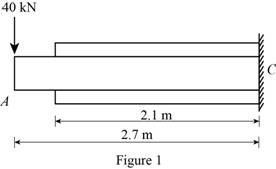
Draw the moment diagram of the above beam as in Figure 2.
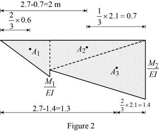
Calculate the moment
Calculate the ratio of
Substitute
Calculate the area
Here,
Substitute 0.6 mm for
Calculate the moment
Calculate the ratio of
Substitute
Calculate the area
Here,
Substitute 2.1 m for
Calculate the area
Substitute
Show the free body diagram of beam by considering the uniformly distributed load as in Figure 3.
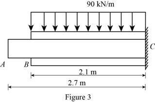
Draw the moment diagram of the above beam as in Figure 4.
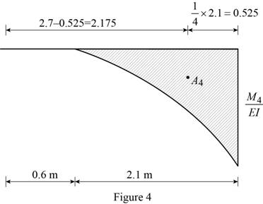
Calculate the moment
Calculate the ratio of
Substitute
Calculate the area
Here,
Substitute
Show the tangent slope and deflection at point A related to reference tangent as in Figure 5.
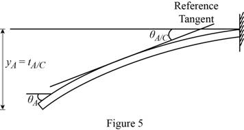
Since the support C has fixed support, the slope
Calculate the slope at the end A related to the fixed end C
Substitute
Calculate the slope at the point A
Substitute 0 for
Thus, the slope
(b)
Find the deflection
Answer to Problem 107P
The deflection
Explanation of Solution
Given information:
The elastic modulus (E) is
The section of the beam is
The dimension of the top plate and bottom plate is
Calculation:
Calculate the deflection at end A related to the fixed end C
Substitute
Calculate the deflection at the point A
Substitute 0 for
Thus, the deflection
Want to see more full solutions like this?
Chapter 9 Solutions
EBK MECHANICS OF MATERIALS


- Q5:(? Design the duct system of the figure below by using the balanced pressure method. The velocity in the duct attached to the AHU must not exceed 5m/s. The pressure loss for each diffuser is equal to 10Pa. 100CFM 100CFM 100CFM ☑ ☑ 40m AHU -16m- 8m- -12m- 57m 250CFM 40m -14m- 26m 36m ☑ 250CFMarrow_forwardA mass of ideal gas in a closed piston-cylinder system expands from 427 °C and 16 bar following the process law, pv1.36 = Constant (p times v to the power of 1.36 equals to a constant). For the gas, initial : final pressure ratio is 4:1 and the initial gas volume is 0.14 m³. The specific heat of the gas at constant pressure, Cp = 0.987 kJ/kg-K and the specific gas constant, R = 0.267 kJ/kg.K. Determine the change in total internal energy in the gas during the expansion. Enter your numerical answer in the answer box below in KILO JOULES (not in Joules) but do not enter the units. (There is no expected number of decimal points or significant figures).arrow_forwardmy ID# 016948724. Please solve this problem step by steparrow_forward
- My ID# 016948724 please find the forces for Fx=0: fy=0: fz=0: please help me to solve this problem step by steparrow_forwardMy ID# 016948724 please solve the proble step by step find the forces fx=o: fy=0; fz=0; and find shear moment and the bending moment diagran please draw the diagram for the shear and bending momentarrow_forwardMy ID#016948724. Please help me to find the moment of inertia lx ly are a please show to solve step by stepsarrow_forward
- My ID# 016948724arrow_forwardPlease do not use any AI tools to solve this question. I need a fully manual, step-by-step solution with clear explanations, as if it were done by a human tutor. No AI-generated responses, please.arrow_forwardPlease do not use any AI tools to solve this question. I need a fully manual, step-by-step solution with clear explanations, as if it were done by a human tutor. No AI-generated responses, please.arrow_forward
 International Edition---engineering Mechanics: St...Mechanical EngineeringISBN:9781305501607Author:Andrew Pytel And Jaan KiusalaasPublisher:CENGAGE L
 Mechanics of Materials (MindTap Course List)Mechanical EngineeringISBN:9781337093347Author:Barry J. Goodno, James M. GerePublisher:Cengage Learning
 Automotive Technology: A Systems Approach (MindTa...Mechanical EngineeringISBN:9781133612315Author:Jack Erjavec, Rob ThompsonPublisher:Cengage Learning
 Principles of Heat Transfer (Activate Learning wi...Mechanical EngineeringISBN:9781305387102Author:Kreith, Frank; Manglik, Raj M.Publisher:Cengage Learning