
Concept explainers
Videos
For the beam and loading shown, (a) express the magnitude and location of the maximum deflection in terms of w0, L, E, and I. (b) Calculate the value of the maximum deflection, assuming that beam AB is a W18 × 50 rolled shape and that w0= 4.5 kips/ft, L = 18 ft, and E = 29 ×106 psi.
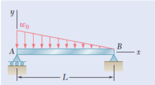
Fig. P9.11
(a)
The magnitude and location of the maximum deflection in terms of
Answer to Problem 11P
The location of the maximum deflection
The magnitude and location of the maximum deflection in terms of
Explanation of Solution
Given that:
The length (L) of the beam is
The load
The young’s modulus E is
Calculation:
Sketch the free body diagram of beam as shown in Figure 1.
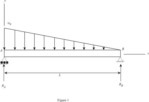
Find the reactions of the beam.
Take the moment at B.
Find the reaction at B.
Take the section 1-1 at x distance from A as shown in Figure 2.
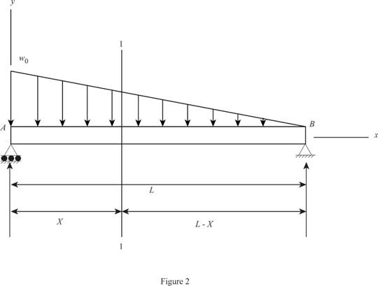
Consider a section
Sketch the section x-x as shown in Figure 3.
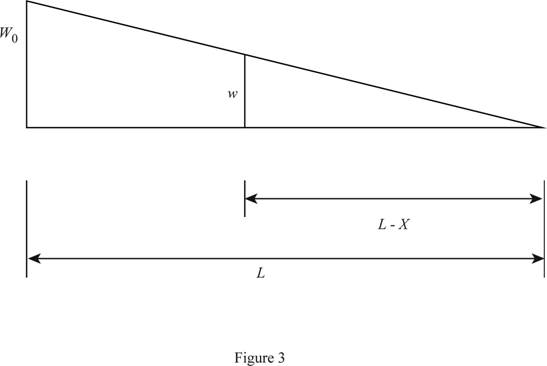
Calculate the intensity of loading w at the section x using similar triangle method as shown below:
Find the shear force using the expression as follows:
Find the shear force using integration:
Find the moment using the relation as follows:
Apply the boundary conditions:
When
When
Substitute 0 for
Write the moment Equation:
Substitute
Integrate the Equation (2).
Integrate the Equation (3).
Apply the boundary condition in
At
Find the
Substitute 0 for x and 0 for
Apply the boundary condition in
At
Find the
Substitute 0 for x and 0 for
Substitute
Differentiate with respect to x in Equation (5).
To find the location of maximum deflection:
Consider the function
Differentiate with respect to z in Equation (7).
Find the value z using Newton-Raphson method as follows:
Show the calculated values of
| 0.22 | -0.01583 | 0.050908 | 0.53100 |
| 0.24 | -0.01479 | 0.053504 | 0.51639 |
| 0.26 | -0.01369 | 0.055796 | 0.50544 |
| 0.28 | -0.01256 | 0.057792 | 0.49730 |
| 0.3 | -0.01138 | 0.0595 | 0.49134 |
| 0.32 | -0.01018 | 0.060928 | 0.48708 |
| 0.34 | -0.00895 | 0.062084 | 0.48415 |
| 0.36 | -0.0077 | 0.062976 | 0.48224 |
| 0.38 | -0.00643 | 0.063612 | 0.48111 |
| 0.4 | -0.00516 | 0.064 | 0.48056 |
| 0.42 | -0.00387 | 0.064148 | 0.48039 |
| 0.44 | -0.00259 | 0.064064 | 0.48045 |
| 0.46 | -0.00131 | 0.063756 | 0.48059 |
| 0.48 | -4.2E-05 | 0.063232 | 0.4807 |
| 0.5000 | 0.0012 | 0.0625 | 0.4806 |
| 0.52 | 0.002456 | 0.061568 | 0.48010 |
Refer to table: 1.
The value of
Find the value of
Substitute
Therefore, he magnitude of the maximum deflection in terms of
Therefore, the location of maximum deflection is
(b)
The value of maximum deflection.
Answer to Problem 11P
The value of maximum deflection is
Explanation of Solution
Calculation:
Convert
The rolled shape section
The value of
Find the maximum deflection using the relation:
Substitute
Thus, the value of maximum deflection is
Want to see more full solutions like this?
Chapter 9 Solutions
EBK MECHANICS OF MATERIALS


- CORRECT AND DETAILED SOLUTION WITH FBD ONLY. I WILL UPVOTE THANK YOU. CORRECT ANSWER IS ALREADY PROVIDED. I NEED FBD A short plate is attached to the center of the shaft as shown. The bottom of the shaft is fixed to the ground.Given: a = 75 mm, h = 125 mm, D = 38 mmP1 = 24 kN, P2 = 28 kN1. Calculate the maximum torsional stress in the shaft, in MPa.2. Calculate the maximum flexural stress in the shaft, in MPa.3. Calculate the maximum horizontal shear stress in the shaft, in MPa.ANSWERS: (1) 167.07 MPa; (2) 679.77 MPa; (3) 28.22 MPaarrow_forwardCORRECT AND DETAILED SOLUTION WITH FBD ONLY. I WILL UPVOTE THANK YOU. CORRECT ANSWER IS ALREADY PROVIDED. I REALLY NEED FBD. The roof truss shown carries roof loads, where P = 10 kN. The truss is consisting of circular arcs top andbottom chords with radii R + h and R, respectively.Given: h = 1.2 m, R = 10 m, s = 2 m.Allowable member stresses:Tension = 250 MPaCompression = 180 MPa1. If member KL has square section, determine the minimum dimension (mm).2. If member KL has circular section, determine the minimum diameter (mm).3. If member GH has circular section, determine the minimum diameter (mm).ANSWERS: (1) 31.73 mm; (2) 35.81 mm; (3) 18.49 mmarrow_forwardPROBLEM 3.23 3.23 Under normal operating condi- tions a motor exerts a torque of magnitude TF at F. The shafts are made of a steel for which the allowable shearing stress is 82 MPa and have diameters of dCDE=24 mm and dFGH = 20 mm. Knowing that rp = 165 mm and rg114 mm, deter- mine the largest torque TF which may be exerted at F. TF F rG- rp B CH TE Earrow_forward
- 1. (16%) (a) If a ductile material fails under pure torsion, please explain the failure mode and describe the observed plane of failure. (b) Suppose a prismatic beam is subjected to equal and opposite couples as shown in Fig. 1. Please sketch the deformation and the stress distribution of the cross section. M M Fig. 1 (c) Describe the definition of the neutral axis. (d) Describe the definition of the modular ratio.arrow_forwardusing the theorem of three moments, find all the moments, I only need concise calculations with minimal explanations. The correct answers are provided at the bottomarrow_forwardMechanics of materialsarrow_forward
- practise questionarrow_forwardCan you provide steps and an explaination on how the height value to calculate the Pressure at point B is (-5-3.5) and the solution is 86.4kPa.arrow_forwardPROBLEM 3.46 The solid cylindrical rod BC of length L = 600 mm is attached to the rigid lever AB of length a = 380 mm and to the support at C. When a 500 N force P is applied at A, design specifications require that the displacement of A not exceed 25 mm when a 500 N force P is applied at A For the material indicated determine the required diameter of the rod. Aluminium: Tall = 65 MPa, G = 27 GPa. Aarrow_forward
 Elements Of ElectromagneticsMechanical EngineeringISBN:9780190698614Author:Sadiku, Matthew N. O.Publisher:Oxford University Press
 Mechanics of Materials (10th Edition)Mechanical EngineeringISBN:9780134319650Author:Russell C. HibbelerPublisher:PEARSON
 Thermodynamics: An Engineering ApproachMechanical EngineeringISBN:9781259822674Author:Yunus A. Cengel Dr., Michael A. BolesPublisher:McGraw-Hill Education
 Control Systems EngineeringMechanical EngineeringISBN:9781118170519Author:Norman S. NisePublisher:WILEY
 Mechanics of Materials (MindTap Course List)Mechanical EngineeringISBN:9781337093347Author:Barry J. Goodno, James M. GerePublisher:Cengage Learning
 Engineering Mechanics: StaticsMechanical EngineeringISBN:9781118807330Author:James L. Meriam, L. G. Kraige, J. N. BoltonPublisher:WILEY