
Concept explainers
Videos
Find the magnitude and location of the largest downward deflection of the beam.
Answer to Problem 61P
The location of the largest downward deflection is
The largest downward deflection of the beam is
Explanation of Solution
Given information:
The modulus of elasticity of the material is
Calculation:
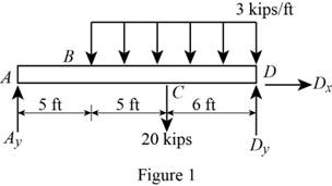
Show the free-body diagram of the beam AD as in Figure 1.
Write the singularity equation for load intensity as follows;
Integrate the equation to find the shear force.
By definition, the change in bending moment with respect to change in distance is shear force.
Integrate the equation to find the bending moment.
Write the second order differential equation as follows;
Here, the moment at the corresponding section is
Substitute
Integrate the equation with respect to x;
Integrate the Equation (2) with respect to x.
Boundary condition 1:
At the point D;
Substitute 16 ft for x and 0 for M in Equation (1).
Boundary condition 2:
At the point A;
Substitute 18.84375 kips for
Boundary condition 3:
At the point D;
Substitute 18.84375 kips for
Refer to Appendix C “The properties of the Rolled-Steel Shapes” in the textbook.
The moment of inertia of the
At point A;
Substitute
At point B;
Substitute
At point C;
Substitute
At point D;
Substitute
The slope changes from negative to positive in the section BC.
The maximum deflection occurs where the slope changes sign. i.e.,
Substitute 0 for
Solve the equation;
Therefore, the location of the largest downward deflection is
At largest deflection point;
Substitute
Therefore, the largest downward deflection of the beam is
Want to see more full solutions like this?
Chapter 9 Solutions
EBK MECHANICS OF MATERIALS


- Water flows in a 1.2-m-diameter finished concrete pipe so that it is completely full and the pressure is constant all along the pipe. If the slope is So = 0.0073, (a) determine the flowrate by using open-channel flow methods. Compare this result with (b) that obtained using the pipe flow methods of Chapter 8 (Use Colebrook formula, Table 8.1, Table 10.1 and assume that Re > 10º). (a) Q = i (b) Q = i m³/s m³/sarrow_forwardfor this 4 figuredarw the Kinematic Diagram:DoF:F=Type/Name ofmechanismEvolution:arrow_forwardTwo channels and two plates are used to formthe column section shown. For b = 200 mm,determine the moments of inertia and theradii of gyration of the combined section withrespect to the centroidal x and y axes.For the section of problem, determine thefirst moment of the upper plate about thecentroidal x-axisarrow_forward
- Determine by direct integration the moment of inertia of theshaded area at right with respect to the x axis shown. Determine by direct integration the moment of inertia of theshaded area of the figure with respect to the y axis shown.arrow_forwardFor the following MATLAB code, I need to answer a few questions. Can you identify the curves as elliptic functions? Which curves reflect the sn, cn, and dn functions?From the curves, determine the maximum amplitudes and the period corresponding toeach angular velocity component. clc; clear all; I = [500; 125; 425]; w = [0.2; 0.1; 0.2]; rev = 0:0.01:10; C = eye(3); % Using ode45 to integrate the KDE and DDE options = odeset('RelTol',1e-9,'AbsTol',1e-9); result = ode45(@K_DDE, rev, [w; I; C(:)], options); v = result.x; % Extracting information from the ode45 solver w = result.y(1:3, :); C_ode = reshape(result.y(7:end, :), [3,3,length(v)]); plot(v, w) xlabel('rev') ylabel('w (rad/s)') legend('w1', 'w2', 'w3') % Functions function dwCdt = K_DDE(~, w_IC) % Extracting the initial condtions to a variable w = w_IC(1:3); I = w_IC(4:6); C = reshape(w_IC(7:end), [3, 3]); I1 = I(1); I2 = I(2); I3 = I(3); K1 = -(I3-I2)/I1; K2 = -(I1-I3)/I2; K3 = -(I2-I1)/I3; %…arrow_forwardplease show a drawing/image and explain how to properly do the question. thanksarrow_forward
- For the four-bar- linkage shown in the following figure. BC=68mm, CD=100mm, AD=120mm. Determine the range of AB to make it a crank-rocker mechanism. B Darrow_forwardall of those 4 fi 1)Draw kinematic diagram: 2)DOF: 3)type/name of mechanism 4)evolution:arrow_forward7.4 Impeller viscometer The rheology of a Penicillium chrysogenum broth is examined using an impeller viscometer. The density of the cell suspension is approximately 1000 kg m³. Samples of broth are stirred under laminar conditions using a Rushton turbine of diameter 4 cm in a glass beaker of diameter 15 cm. The average shear rate generated by the impeller is greater than the stirrer speed by a factor of about 10.2. When the stirrer shaft is attached to a device for measuring torque and rotational speed, the following results are recorded. Stirrer speed (s¹) Torque (Nm) 0.185 3.57 × 10⁻⁶ 0.163 3.45 × 10⁻⁶ 0.126 3.31 x 10⁻⁶ 0.111 3.20×10⁻⁶ Can the rheology be described using a power-law model? If so, evaluate K and n.arrow_forward
- (read image)arrow_forward(read image) Answer Providedarrow_forwardThis is part B Part A's question and answer was find moment of inertia (Ix = 3.90×10^5) and radius of gyration (kx = 21.861) Determine the centroid ( x & y ) of the I-section, Calculate the moment of inertia of the section about itscentroidal x & y axes. How or why is this result different fromthe result of a previous problem?arrow_forward
 Elements Of ElectromagneticsMechanical EngineeringISBN:9780190698614Author:Sadiku, Matthew N. O.Publisher:Oxford University Press
 Mechanics of Materials (10th Edition)Mechanical EngineeringISBN:9780134319650Author:Russell C. HibbelerPublisher:PEARSON
 Thermodynamics: An Engineering ApproachMechanical EngineeringISBN:9781259822674Author:Yunus A. Cengel Dr., Michael A. BolesPublisher:McGraw-Hill Education
 Control Systems EngineeringMechanical EngineeringISBN:9781118170519Author:Norman S. NisePublisher:WILEY
 Mechanics of Materials (MindTap Course List)Mechanical EngineeringISBN:9781337093347Author:Barry J. Goodno, James M. GerePublisher:Cengage Learning
 Engineering Mechanics: StaticsMechanical EngineeringISBN:9781118807330Author:James L. Meriam, L. G. Kraige, J. N. BoltonPublisher:WILEY