
Concept explainers
Videos
Use the method of superposition to solve the following problems and assume that the flexural rigidity El of each beam is constant.
9.83 and 9.84 For the beam shown, determine the reaction at B.
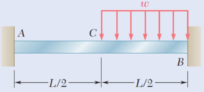
Fig. P9.83
Find the reaction at point B of the beam using superposition method.
Answer to Problem 83P
The vertical reaction at point B is
The moment at point B is
Explanation of Solution
The flexural rigidity of the beam is EI.
Convert the beam into two sections as in Figure 1.
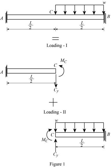
Consider portion AC of the beam:
Show the free-body diagram of the superimposed beam as in Figure 2.
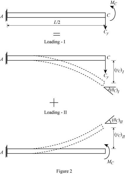
Loading I:
The downward reaction
Refer to case 1 in Appendix D “Beam Deflections and Slopes” in the textbook.
Write the equation for slope and deflection for point load acting in a cantilever beam as follows;
Find the deflection at point C due to vertical reaction as follows;
Find the slope at point C due to vertical reaction as follows;
Loading II:
The counter-clockwise moment is acting at point C.
Refer to case 3 in Appendix D “Beam Deflections and Slopes” in the textbook.
Write the equation for slope and deflection for moment acting in a cantilever beam as follows;
Find the deflection at point C due to moment as follows;
Find the slope at point C due to moment as follows;
Find the deflection at point C as follows;
Substitute
Find the slope at point C as follows;
Substitute
Consider portion CB of the beam:
Show the free-body diagram of the superimposed beam as in Figure 3.
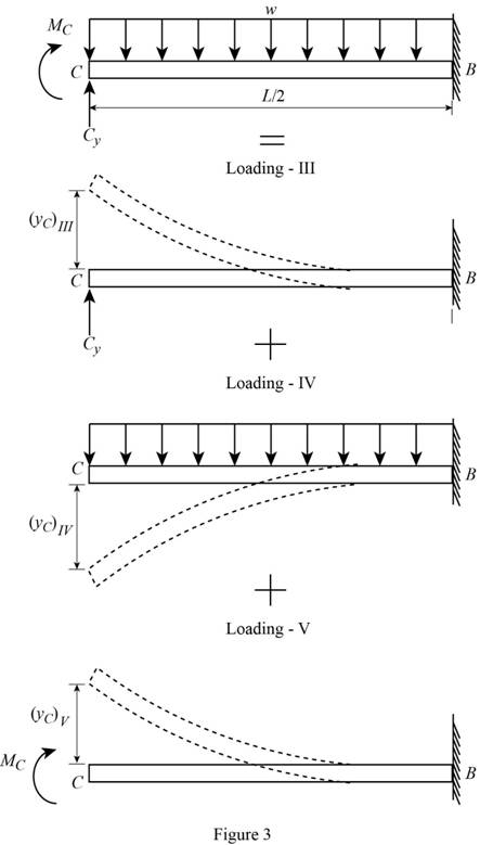
Loading III:
The upward reaction
Refer to case 1 in Appendix D “Beam Deflections and Slopes” in the textbook.
Write the equation for slope and deflection for point load acting in a cantilever beam as follows;
Find the deflection at point C due to vertical reaction as follows;
Find the slope at point C due to vertical reaction as follows;
Loading IV:
The downward uniformly distributed load (udl) is spread throughout the portion BC.
Refer to case 2 in Appendix D “Beam Deflections and Slopes” in the textbook.
Write the equation for slope and deflection for udl spread throughout the cantilever beam as follows;
Find the deflection at point C due to udl as follows;
Find the slope at point C due to udl as follows;
Loading IV:
The clockwise moment is acting at point C.
Refer to case 3 in Appendix D “Beam Deflections and Slopes” in the textbook.
Write the equation for slope and deflection for moment acting in a cantilever beam as follows;
Find the deflection at point C due to moment as follows;
Find the slope at point C due to moment as follows;
Find the deflection at point C as follows;
Substitute
Find the slope at point C as follows;
Substitute
The resultant deflection at point C is equal.
Equate the equations (1) and (3).
The resultant slope at point C is equal.
Equate the equations (2) and (4).
Show the free-body diagram of the portion CB as in Figure 4.
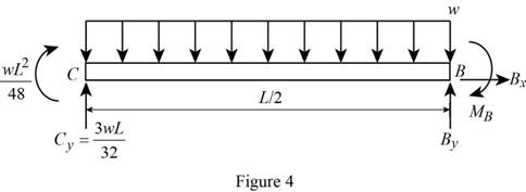
Find the vertical reaction at point B by resolving the vertical component of forces.
Find the moment at point B by taking moment about point B.
Therefore,
The vertical reaction at point B is
The moment at point B is
Want to see more full solutions like this?
Chapter 9 Solutions
EBK MECHANICS OF MATERIALS


- 32 mm 32 mm b' c' C 32 mm 32 mm b PROBLEM 6.41 a The extruded beam shown has a uniform wall thickness of 3 mm. Knowing that the vertical shear in the beam is 9 kN, determine the shearing stress at each of the five points indicated.arrow_forwardIn a structural reliability problem, the resistance (capacity) R and load effect (demand) S random variables associated with a failure mode of the structure of interest are normally distributed and statistically independent with the following probability distribution parameters (or statistics) in consistent units: MR = 12, σR = 3 μs = 5, σs = 2 (a) Determine the exact probability of failure pF ·arrow_forwardThe resistance R and load effect S for a given failure mode are statistically independent random variables with marginal PDF's 1 fR (r) = 0≤r≤100 100' fs(s)=0.05e-0.05s (a) Determine the probability of failure by computing the probability content of the failure domain defined as {rarrow_forwardPlease solve this problem as soon as possible My ID# 016948724arrow_forwardThe gears shown in the figure have a diametral pitch of 2 teeth per inch and a 20° pressure angle. The pinion rotates at 1800 rev/min clockwise and transmits 200 hp through the idler pair to gear 5 on shaft c. What forces do gears 3 and 4 transmit to the idler shaft? TS I y 18T 32T This a 12 x 18T C 48T 5arrow_forwardQuestion 1. Draw 3 teeth for the following pinion and gear respectively. The teeth should be drawn near the pressure line so that the teeth from the pinion should mesh those of the gear. Drawing scale (1:1). Either a precise hand drawing or CAD drawing is acceptable. Draw all the trajectories of the involute lines and the circles. Specification: 18tooth pinion and 30tooth gear. Diameter pitch=P=6 teeth /inch. Pressure angle:20°, 1/P for addendum (a) and 1.25/P for dedendum (b). For fillet, c=b-a.arrow_forward5. The figure shows a gear train. There is no friction at the bearings except for the gear tooth forces. The material of the milled gears is steel having a Brinell hardness of 170. The input shaft speed (n2) is 800 rpm. The face width and the contact angle for all gears are 1 in and 20° respectively. In this gear set, the endurance limit (Se) is 15 kpsi and nd (design factor) is 2. (a) Find the revolution speed of gear 5. (b) Determine whether each gear satisfies the design factor of 2.0 for bending fatigue. (c) Determine whether each gear satisfies the design factor of 2.0 for surface fatigue (contact stress). (d) According to the computation results of the questions (b) and (c), explain the possible failure mechanisms for each gear. N4=28 800rpm N₁=43 N5=34 N₂=14 P(diameteral pitch)=8 for all gears Coupled to 2.5hp motorarrow_forward1. The rotating steel shaft is simply supported by bearings at points of B and C, and is driven by a spur gear at D, which has a 6-in pitch diameter. The force F from the drive gear acts at a pressure angle of 20°. The shaft transmits a torque to point A of TA =3000 lbĘ in. The shaft is machined from steel with Sy=60kpsi and Sut=80 kpsi. (1) Draw a shear force diagram and a bending moment diagram by F. According to your analysis, where is the point of interest to evaluate the safety factor among A, B, C, and D? Describe the reason. (Hint: To find F, the torque Tд is generated by the tangential force of F (i.e. Ftangential-Fcos20°) When n=2.5, K=1.8, and K₁ =1.3, determine the diameter of the shaft based on (2) static analysis using DE theory (note that fatigue stress concentration factors need to be used for this question because the loading condition is fatigue) and (3) a fatigue analysis using modified Goodman. Note) A standard diameter is not required for the questions. 10 in Darrow_forward3 N2=28 P(diametral pitch)=8 for all gears Coupled to 25 hp motor N3=34 Full depth spur gears with pressure angle=20° N₂=2000 rpm (1) Compute the circular pitch, the center-to-center distance, and base circle radii. (2) Draw the free body diagram of gear 3 and show all the forces and the torque. (3) In mounting gears, the center-to-center distance was reduced by 0.1 inch. Calculate the new values of center-to-center distance, pressure angle, base circle radii, and pitch circle diameters. (4)What is the new tangential and radial forces for gear 3? (5) Under the new center to center distance, is the contact ratio (mc) increasing or decreasing?arrow_forward2. A flat belt drive consists of two 4-ft diameter cast-iron pulleys spaced 16 ft apart. A power of 60 hp is transmitted by a pulley whose speed is 380 rev/min. Use a service factor (Ks) pf 1.1 and a design factor 1.0. The width of the polyamide A-3 belt is 6 in. Use CD=1. Answer the following questions. (1) What is the total length of the belt according to the given geometry? (2) Find the centrifugal force (Fc) applied to the belt. (3) What is the transmitted torque through the pulley system given 60hp? (4) Using the allowable tension, find the force (F₁) on the tight side. What is the tension at the loose side (F2) and the initial tension (F.)? (5) Using the forces, estimate the developed friction coefficient (f) (6) Based on the forces and the given rotational speed, rate the pulley set. In other words, what is the horse power that can be transmitted by the pulley system? (7) To reduce the applied tension on the tight side, the friction coefficient is increased to 0.75. Find out the…arrow_forwardThe tooth numbers for the gear train illustrated are N₂ = 24, N3 = 18, №4 = 30, №6 = 36, and N₁ = 54. Gear 7 is fixed. If shaft b is turned through 5 revolutions, how many turns will shaft a make? a 5 [6] barrow_forwardCE-112 please solve this problem step by step and give me the correct answerarrow_forwardarrow_back_iosSEE MORE QUESTIONSarrow_forward_ios
 International Edition---engineering Mechanics: St...Mechanical EngineeringISBN:9781305501607Author:Andrew Pytel And Jaan KiusalaasPublisher:CENGAGE L
 Mechanics of Materials (MindTap Course List)Mechanical EngineeringISBN:9781337093347Author:Barry J. Goodno, James M. GerePublisher:Cengage Learning
 Principles of Heat Transfer (Activate Learning wi...Mechanical EngineeringISBN:9781305387102Author:Kreith, Frank; Manglik, Raj M.Publisher:Cengage Learning