
Videos
A pure jet engine propels an aircraft at 240 m/s through air at 45 kPa and −13°C. The inlet diameter of this engine is 1.6 m, the compressor pressure ratio is 13, and the temperature at the turbine inlet is 557°C. Determine the velocity at the exit of this engine’s nozzle and the thrust produced. Assume ideal operation for all components and constant specific heats at room temperature.
The velocity at the exit of this engine’s nozzle and the thrust produced.
Answer to Problem 132P
The velocity at the exit of this engine’s nozzle is
The thrust produced by the engine is
Explanation of Solution
Draw the
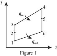
Consider that the aircraft is stationary, and the velocity of air moving towards the aircraft is
Diffuser:
Write the expression for the energy balance equation for the diffuser.
Here, the rate of energy entering the system is
Write the temperature and pressure relation for the process 1-2.
Here, the specific heat ratio of air is k, pressure at state 1 is
Compressor:
Write the pressure relation using the pressure ratio for the process 2-3.
Here, the pressure ratio is
Write the temperature and pressure relation for the process 2-3.
Here, temperate at state 3 is
Turbine:
Write the temperature relation for the compressor and turbine.
Here, the specific heat at constant pressure is
Nozzle:
Write the temperature and pressure relation for the isentropic process 4-6.
Here, pressure at state 6 is
Write the energy balance equation for the nozzle.
Write the expression to calculate the specific volume at state 1
Here, gas constant is
Write the expression to calculate the mass flow rate of propeller
Here, propeller diameter is
Write the expression to calculate the thrust force generated by the propeller
Here, the thrust force produced by engine is
Conclusion.
From Table A-2a, “Ideal-gas specific heats of various common gases”, obtain the following values for air at room temperature.
The rate of change in the energy of the system
Substitute
Here, inlet velocity is
Substitute 0 for
Substitute
Substitute 13 for
Substitute
Substitute
Substitute
The rate of change in the energy of the system
Substitute
Here, velocity at stat 5 is
Since,
Substitute
Thus, the velocity at the exit of this engine’s nozzle is
Substitute
Substitute
Substitute
Thus, the thrust produced by the engine is
Want to see more full solutions like this?
Chapter 9 Solutions
EBK THERMODYNAMICS: AN ENGINEERING APPR


- Determine the moments of the force about the x and the a axes. O 4 m F = {-40i +20j + 10k} N 3 m 6 m aarrow_forward6. A part of the structure for a factory automation system is a beam that spans 30.0 in as shown in Figure P5-6. Loads are applied at two points, each 8.0 in from a support. The left load F₁ = 1800 lb remains constantly applied, while the right load F₂ = 1800 lb is applied and removed fre- quently as the machine cycles. Evaluate the beam at both B and C. A 8 in F₁ = 1800 lb 14 in F2 = 1800 lb 8 in D RA B C 4X2X1/4 Steel tube Beam cross section RDarrow_forward30. Repeat Problem 28, except using a shaft that is rotating and transmitting a torque of 150 N⚫m from the left bear- ing to the middle of the shaft. Also, there is a profile key- seat at the middle under the load.arrow_forward
- 28. The shaft shown in Figure P5-28 is supported by bear- ings at each end, which have bores of 20.0 mm. Design the shaft to carry the given load if it is steady and the shaft is stationary. Make the dimension a as large as pos- sible while keeping the stress safe. Determine the required d = 20mm D = ? R = ?| 5.4 kN d=20mm Length not to scale -a = ?- +а= a = ? + -125 mm- -250 mm- FIGURE P5-28 (Problems 28, 29, and 30)arrow_forward12. Compute the estimated actual endurance limit for SAE 4130 WQT 1300 steel bar with a rectangular cross sec- tion of 20.0 mm by 60 mm. It is to be machined and subjected to repeated and reversed bending stress. A reli- ability of 99% is desired.arrow_forward28. The shaft shown in Figure P5-28 is supported by bear- ings at each end, which have bores of 20.0 mm. Design the shaft to carry the given load if it is steady and the shaft is stationary. Make the dimension a as large as pos- sible while keeping the stress safe. Determine the required d = 20mm D = ? R = ?| 5.4 kN d=20mm Length not to scale -a = ?- +а= a = ? + -125 mm- -250 mm- FIGURE P5-28 (Problems 28, 29, and 30)arrow_forward
- 2. A strut in a space frame has a rectangular cross section of 10.0 mm by 30.0 mm. It sees a load that varies from a tensile force of 20.0 kN to a compressive force of 8.0 kN.arrow_forwardfind stress at Qarrow_forwardI had a theoretical question about attitude determination. In the attached images, I gave two axis and angles. The coefficient of the axes are the same and the angles are the same. The only difference is the vector basis. Lets say there is a rotation going from n hat to b hat. Then, you introduce a intermediate rotation s hat. So, I want to know if the DCM produced from both axis and angles will be the same or not. Does the vector basis affect the numerical value of the DCM? The DCM formula only cares about the coefficient of the axis and the angle. So, they should be the same right?arrow_forward
- 3-15. A small fixed tube is shaped in the form of a vertical helix of radius a and helix angle y, that is, the tube always makes an angle y with the horizontal. A particle of mass m slides down the tube under the action of gravity. If there is a coefficient of friction μ between the tube and the particle, what is the steady-state speed of the particle? Let y γ 30° and assume that µ < 1/√3.arrow_forwardThe plate is moving at 0.6 mm/s when the force applied to the plate is 4mN. If the surface area of the plate in contact with the liquid is 0.5 m^2, deterimine the approximate viscosity of the liquid, assuming that the velocity distribution is linear.arrow_forward3-9. Given that the force acting on a particle has the following components: Fx = −x + y, Fy = x − y + y², F₂ = 0. Solve for the potential energy V. -arrow_forward
 Elements Of ElectromagneticsMechanical EngineeringISBN:9780190698614Author:Sadiku, Matthew N. O.Publisher:Oxford University Press
 Mechanics of Materials (10th Edition)Mechanical EngineeringISBN:9780134319650Author:Russell C. HibbelerPublisher:PEARSON
 Thermodynamics: An Engineering ApproachMechanical EngineeringISBN:9781259822674Author:Yunus A. Cengel Dr., Michael A. BolesPublisher:McGraw-Hill Education
 Control Systems EngineeringMechanical EngineeringISBN:9781118170519Author:Norman S. NisePublisher:WILEY
 Mechanics of Materials (MindTap Course List)Mechanical EngineeringISBN:9781337093347Author:Barry J. Goodno, James M. GerePublisher:Cengage Learning
 Engineering Mechanics: StaticsMechanical EngineeringISBN:9781118807330Author:James L. Meriam, L. G. Kraige, J. N. BoltonPublisher:WILEY