
Microelectronics: Circuit Analysis and Design
4th Edition
ISBN: 9780073380643
Author: Donald A. Neamen
Publisher: McGraw-Hill Companies, The
expand_more
expand_more
format_list_bulleted
Concept explainers
Videos
Textbook Question
Chapter 9, Problem D9.55P
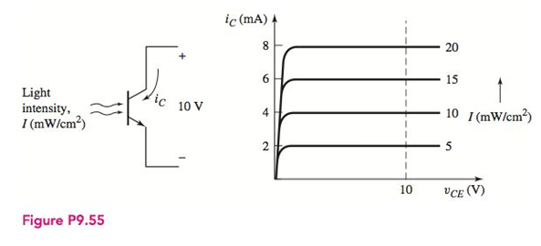
Figure P9.55 shows a phototransistor that converts light intensity into an output current. The transistor must be biased as shown. The transistor output versus input characteristics are shown. Design a current-to-voltage converter toproduce an output voltage between 0 and 8 V for an input light intensity between 0and
Expert Solution & Answer
Want to see the full answer?
Check out a sample textbook solution
Students have asked these similar questions
Please no AI response.
I have uploaded the rules, please explain step by step and which rule you have applied
I have uploaded the rules, please explain step by step and which rule you have applied
Chapter 9 Solutions
Microelectronics: Circuit Analysis and Design
Ch. 9 - Design an ideal inverting op-amp circuit such that...Ch. 9 - Design an ideal inverting op-amp circuit with a...Ch. 9 - (a) An inverting op-amp circuit is to be designed...Ch. 9 - (a) Design an ideal inverting op-amp circuit such...Ch. 9 - Prob. 9.2TYUCh. 9 - Consider an inverting op-amp circuit as shown in...Ch. 9 - (a) Design an inverting summing amplifier that...Ch. 9 - Consider an ideal summing amplifier as shown in...Ch. 9 - Design the summing amplifier in Figure 9.14 to...Ch. 9 - (a) Design a noninverting amplifier such that the...
Ch. 9 - The noninverting op-amp in Figure 9.15 has a...Ch. 9 - Use superposition to determine the output voltage...Ch. 9 - Consider the voltage-to-current converter shown in...Ch. 9 - Consider the difference amplifier in Figure...Ch. 9 - In the difference amplifier shown in Figure...Ch. 9 - For the instrumentation amplifier in Figure 9.26,...Ch. 9 - An integrator with input and output voltages that...Ch. 9 - A current source has an output impedance of...Ch. 9 - Design the voltage-to-current converter shown in...Ch. 9 - All parameters associated with the instrumentation...Ch. 9 - Design the instrumentation amplifier in Figure...Ch. 9 - An integrator is driven by the series of pulses...Ch. 9 - Consider the summing op-amp in Figure 9.40. Let...Ch. 9 - Consider the bridge circuit in Figure 9.46. The...Ch. 9 - The resistance R in the bridge circuit in Figure...Ch. 9 - Describe the ideal op-amp model and describe the...Ch. 9 - Prob. 2RQCh. 9 - Describe the operation and characteristics of the...Ch. 9 - What is the concept of virtual ground?Ch. 9 - What is the significance of a zero output...Ch. 9 - When a finite op-amp gain is taken into account,...Ch. 9 - Prob. 7RQCh. 9 - Describe the operation and characteristics of the...Ch. 9 - Describe the voltage follower. What are the...Ch. 9 - What is the input resistance of an ideal...Ch. 9 - Prob. 11RQCh. 9 - Describe the operation and characteristics of an...Ch. 9 - Describe the operation and characteristics of an...Ch. 9 - Describe the operation and characteristics of an...Ch. 9 - Assume an op-amp is ideal, except for having a...Ch. 9 - The op-amp in the circuit shown in Figure P9.2 is...Ch. 9 - An op-amp is in an open-loop configuration as...Ch. 9 - Consider the equivalent circuit of the op-amp...Ch. 9 - Consider the ideal inverting op-amp circuit shown...Ch. 9 - Assume the op-amps in Figure P9.6 are ideal. Find...Ch. 9 - Consider an ideal inverting op-amp with R2=100k...Ch. 9 - (a) Design an inverting op-amp circuit with a...Ch. 9 - Consider an ideal op-amp used in an inverting...Ch. 9 - Consider the inverting amplifier shown in Figure...Ch. 9 - (a) Design an inverting op-amp circuit with a...Ch. 9 - (a) Design an inverting op-amp circuit such that...Ch. 9 - (a) In an inverting op-amp circuit, the nominal...Ch. 9 - (a) The input to the circuit shown in Figure P9.14...Ch. 9 - Design an inverting amplifier to provide a nominal...Ch. 9 - The parameters of the two inverting op-amp...Ch. 9 - Design the cascade inverting op-amp circuit in...Ch. 9 - Design an amplifier system with three inverting...Ch. 9 - Consider the circuit shown in Figure P9.19. (a)...Ch. 9 - The inverting op-amp shown in Figure 9.9 has...Ch. 9 - (a)An op-amp with an open-loop gain of Aod=7103 is...Ch. 9 - (a) For the ideal inverting op-amp circuit with...Ch. 9 - An ideal inverting op-amp circuit is to be...Ch. 9 - For the op-amp circuit shown in Figure P9.25,...Ch. 9 - The inverting op-amp circuit in Figure 9.9 has...Ch. 9 - (a) Consider the op-amp circuit in Figure P9.27....Ch. 9 - The circuit in Figure P9.28 is similar to the...Ch. 9 - Consider the ideal inverting summing amplifier in...Ch. 9 - (a) Design an ideal inverting summing amplifier to...Ch. 9 - Design an ideal inverting summing amplifier to...Ch. 9 - Consider the summing amplifier in Figure 9.14 with...Ch. 9 - The parameters for the summing amplifier in Figure...Ch. 9 - (a) Design an ideal summing op-amp circuit to...Ch. 9 - An ideal three-input inverting summing amplifier...Ch. 9 - A summing amplifier can be used as a...Ch. 9 - Consider the circuit in Figure P9.38. (a) Derive...Ch. 9 - Consider the summing amplifier in Figure 9.14(a)....Ch. 9 - Consider the ideal noninverting op-amp circuit in...Ch. 9 - (a) Design an ideal noninverting op-amp circuit...Ch. 9 - Consider the noninverting amplifier in Figure...Ch. 9 - For the circuit in Figure P9.43, the input voltage...Ch. 9 - Determine vO as a function of vI1 and vI2 for the...Ch. 9 - Consider the ideal noninverting op-amp circuit in...Ch. 9 - (a) Derive the expression for the closed-loop...Ch. 9 - The circuit shown in Figure P9.47 can be used as a...Ch. 9 - (a) Determine the closed-loop voltage gain...Ch. 9 - For the amplifier in Figure P9.49, determine (a)...Ch. 9 - Consider the voltage-follower circuit in Figure...Ch. 9 - (a) Consider the ideal op-amp circuit shown in...Ch. 9 - (a) Assume the op-amp in the circuit in Figure...Ch. 9 - Prob. 9.53PCh. 9 - A current-to-voltage converter is shown in Figure...Ch. 9 - Figure P9.55 shows a phototransistor that converts...Ch. 9 - The circuit in Figure P9.56 is an analog voltmeter...Ch. 9 - Consider the voltage-to-current converter in...Ch. 9 - The circuit in Figure P9.58 is used to drive an...Ch. 9 - Figure P9.59 is used to calculate the resistance...Ch. 9 - Consider the op-amp difference amplifier in Figure...Ch. 9 - Consider the differential amplifier shown in...Ch. 9 - Consider the differential amplifier shown in...Ch. 9 - Let R=10k in the differential amplifier in Figure...Ch. 9 - Consider the circuit shown in Figure P9.64. (a)...Ch. 9 - The circuit in Figure P9.65 is a representation of...Ch. 9 - Consider the adjustable gain difference amplifier...Ch. 9 - Assume the instrumentation amplifier in Figure...Ch. 9 - Consider the circuit in Figure P9.68. Assume ideal...Ch. 9 - Consider the circuit in Figure P969. Assume ideal...Ch. 9 - The instrumentation amplifier in Figure 9.26 has...Ch. 9 - Design the instrumentation amplifier in Figure...Ch. 9 - All parameters associated with the instrumentation...Ch. 9 - The parameters in the integrator circuit shown in...Ch. 9 - Consider the ideal op-amp integrator. Assume the...Ch. 9 - The circuit in Figure P9.75 is a first-order...Ch. 9 - (a) Using the results of Problem 9.75, design the...Ch. 9 - The circuit shown in Figure P9.77 is a first-order...Ch. 9 - (a) Using the results of Problem 9.77, design the...Ch. 9 - Prob. 9.79PCh. 9 - Consider the circuit in Figure 9.35. The diode...Ch. 9 - In the circuit in Figure P9.81, assume that Q1 and...Ch. 9 - Consider the circuit in Figure 9.36. The diode...Ch. 9 - Design an op-amp summer to produce the output...Ch. 9 - Design an op-amp summer to produce an output...Ch. 9 - Design a voltage reference source as shown in...Ch. 9 - Consider the voltage reference circuit in Figure...Ch. 9 - Consider the bridge circuit in Figure P9.87. The...Ch. 9 - Consider the bridge circuit in Figure 9.46. The...
Knowledge Booster


Learn more about
Need a deep-dive on the concept behind this application? Look no further. Learn more about this topic, electrical-engineering and related others by exploring similar questions and additional content below.Similar questions
- I have uploaded the rules, please explain step by step and which rule you have appliedarrow_forwardUsing the CCS Compiler method to solve this question Write a PIC16F877A program that flash ON the 8-LED's connected to port-B by using two switches connected to port-D (Do & D₁) as shown in figure below, according to the following scenarios: (Hint: Use 500ms delay for each case with 4MHz frequency) 1. When Do=1 then B₁,B3,B7 are ON. 2. When Do 0 then Bo,B2, B4, B5, B6 are ON. 3. When D₁=1 then B4,B,,B6,B7 are ON. 4. When D₁-0 then Bo,B1,B2,B3 are ON.arrow_forwardUse the ramp generator circuit in Fig. B2a to generate the waveform shown in Fig. B2b. Write four equations relating resistors R1, R2, R3, capacitor C and voltages Vs, VR and VA.to the waveform parameters T₁, T, Vcm and Vm- If R = R2 = R3, R₁ = 2R, C = 1 nF, Vcm = 2 V and Vm = 1 V, T₁ = 2 μs and T = 10 μs solve for the values of R, Vs, VR and VA using your equations from part a(i). VR C +VA R3 V₂ Vo мат R1 VsO+ V₁ R₂ Figure B2a Vout Vcm+Vm Vcm Vcm-Vm 0 T₁ T 2T time Figure B2barrow_forward
- The circuit in Figure B1a is a common analogue circuit block. Explain why you would need such a circuit. Draw another circuit in which you use the current flowing in this loop to bias a common source amplifier. This circuit is not ideal for standard CMOS technologies due to threshold shift. Why? Draw an improved version of this circuit to make it better. VDD (W)P MA M3. (), REF (쁜)~ M₁ M2 lout 시~ Rsarrow_forward23bcarrow_forwardDraw the small-signal equivalent circuit of a single transistor amplifier given in figure B1b. Assume the current source to be ideal. Determine the Open-loop transfer function, pole frequency and gain-bandwidth product all in terms of transistor parameters 9m, To and CL. If the load capacitance is 1pF and the necessary unity gain frequency is 600MHz, find the gm for this transistor. V₁ V₁ CLarrow_forward
arrow_back_ios
SEE MORE QUESTIONS
arrow_forward_ios
Recommended textbooks for you
 Introductory Circuit Analysis (13th Edition)Electrical EngineeringISBN:9780133923605Author:Robert L. BoylestadPublisher:PEARSON
 Delmar's Standard Textbook Of ElectricityElectrical EngineeringISBN:9781337900348Author:Stephen L. HermanPublisher:Cengage Learning
 Programmable Logic ControllersElectrical EngineeringISBN:9780073373843Author:Frank D. PetruzellaPublisher:McGraw-Hill Education
 Fundamentals of Electric CircuitsElectrical EngineeringISBN:9780078028229Author:Charles K Alexander, Matthew SadikuPublisher:McGraw-Hill Education
 Electric Circuits. (11th Edition)Electrical EngineeringISBN:9780134746968Author:James W. Nilsson, Susan RiedelPublisher:PEARSON
 Engineering ElectromagneticsElectrical EngineeringISBN:9780078028151Author:Hayt, William H. (william Hart), Jr, BUCK, John A.Publisher:Mcgraw-hill Education,
Introductory Circuit Analysis (13th Edition)
Electrical Engineering
ISBN:9780133923605
Author:Robert L. Boylestad
Publisher:PEARSON
Delmar's Standard Textbook Of Electricity
Electrical Engineering
ISBN:9781337900348
Author:Stephen L. Herman
Publisher:Cengage Learning
Programmable Logic Controllers
Electrical Engineering
ISBN:9780073373843
Author:Frank D. Petruzella
Publisher:McGraw-Hill Education
Fundamentals of Electric Circuits
Electrical Engineering
ISBN:9780078028229
Author:Charles K Alexander, Matthew Sadiku
Publisher:McGraw-Hill Education
Electric Circuits. (11th Edition)
Electrical Engineering
ISBN:9780134746968
Author:James W. Nilsson, Susan Riedel
Publisher:PEARSON
Engineering Electromagnetics
Electrical Engineering
ISBN:9780078028151
Author:Hayt, William H. (william Hart), Jr, BUCK, John A.
Publisher:Mcgraw-hill Education,
Electrical Engineering: Ch 5: Operational Amp (2 of 28) Inverting Amplifier-Basic Operation; Author: Michel van Biezen;https://www.youtube.com/watch?v=x2xxOKOTwM4;License: Standard YouTube License, CC-BY