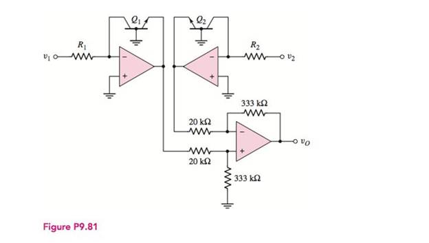
In the circuit in Figure P9.81, assume that

To show: The expression for the output voltageis
Explanation of Solution
Calculation:
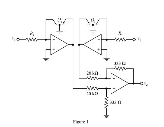
The given diagram is shown in Figure 1.

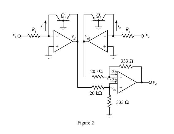
Mark the current directions, voltages and redraw the circuit.
The required diagram is shown in Figure 2

The expression for the voltage
For an ideal op-amp the voltage at both the input terminals are equal and is given by,
Substitute
Apply KCL at the inverting terminals of the lower op amp.
Substitute
The expression for the current
The expression for the current through the resistance
Substitute
The expression for the current
The expression for the current
Substitute
The expression for the transistor current is given by,
Substitute
Substitute
Substitute
Substitute
Therefore, theexpression for the output voltage is
Want to see more full solutions like this?
Chapter 9 Solutions
Microelectronics: Circuit Analysis and Design
Additional Engineering Textbook Solutions
Automotive Technology: Principles, Diagnosis, And Service (6th Edition) (halderman Automotive Series)
Electric Circuits. (11th Edition)
Database Concepts (8th Edition)
Vector Mechanics for Engineers: Statics and Dynamics
Degarmo's Materials And Processes In Manufacturing
Modern Database Management
- A Digital Filter is described by the following. difference equation: Y(n)=0.5x(n) 0.5(n-2) - Find the transfer function ..arrow_forwardQ4) answer just two from three the following terms: A) Design ADC using the successive method if the Vmax=(3) volt, Vmin=(-2) volt, demonstrate the designing system for vin-1.2 volt.arrow_forward(a) For a voltage phasor V(jω) and a current phasor I(jω), give an expression for the complex power.(b)Give three examples of how real (average) power might be dissipated.(c)A time-domain voltage is defined by the expression v(t)= 5 cos(πt/3) V. When this is applied across an impedance Z = 4∠60° Ω, determine:(i)The instantaneous power.(ii)The average power.arrow_forward
- Consider the LTI system with the input x(t) = e^28(t) and the impulse response h(t) = e−²tu(t). a) Determine the Laplace transform of x(t) and h(t). (10 marks) b) Using convolutional property, determine the Laplace transform and the ROC for the output response y(t).arrow_forward解出R1和R2arrow_forwardAccording to the book the answers are m= 30 and n = 5 and number of switch blocks is 220arrow_forward
- find reactive power demand , capacitor bank provides and overcompenstationarrow_forward(A) Consider a communication system where the number of successful transsions out of 10 trials follows a binomial distribution. The success probability for each triat is 0,95, Let X be the random variable representing the number of successful transmissions. -Sketch the cumulative distribution function (CDF) of the distribution. 2- Find Skewness coefficients and check if the distribution is symmetrical or skewed to the right or left. 3- Find kurtosis coefficients, Check if the distribution is mesokurtic, leptokurtic or platykurtic. 4- Find the probability of getting at most eigh. successful transmissions. 5- Find the probability P(20 with a mean 2-1 calculate the probability that the noise is greater than 3 units.arrow_forwardQ4: (A) Find the mean of a random variable X if S f(x)= 2x 0 2 for 0arrow_forward(A) Suopces the current measurements in a strip of wire are normally distributed with ca-10(mA) and a varieocom (mA)² 1- What is the probability that a current measurement lies between 7.4 and 11.6 mA? 2-Drew the probability density function of the current distribution. (8) A factory produces light bulbs with a koown probability of P(D)-0.08 that & bulo is dalective. If a bulb is defective, the probability that the quality control test detects it is defective is P(TID)-0.90. Conversely, if a bulb is not defective, the probability that the test Telesly indicaton k as defective is P(TID)-0.05. calculate the probability that a light b is notually defective given that the test result is positive, F(DIT).arrow_forwardTitle: Modelling and Simulating Boost Converter Battery Charging Powered by PV Solar Question: I need a MATLAB/Simulink model for a Boost Converter used to charge a battery, powered by a PV solar panel. The model should include: 1. A PV solar panel as the input power source. 2. A Boost Converter circuit for voltage regulation. 3. A battery charging system. 4. Simulation results showing voltage, current, and efficiency of the system. Please provide the Simulink file and any necessary explanations.arrow_forwardPlease answerarrow_forwardarrow_back_iosSEE MORE QUESTIONSarrow_forward_ios
 Introductory Circuit Analysis (13th Edition)Electrical EngineeringISBN:9780133923605Author:Robert L. BoylestadPublisher:PEARSON
 Delmar's Standard Textbook Of ElectricityElectrical EngineeringISBN:9781337900348Author:Stephen L. HermanPublisher:Cengage Learning
 Programmable Logic ControllersElectrical EngineeringISBN:9780073373843Author:Frank D. PetruzellaPublisher:McGraw-Hill Education
 Fundamentals of Electric CircuitsElectrical EngineeringISBN:9780078028229Author:Charles K Alexander, Matthew SadikuPublisher:McGraw-Hill Education
 Electric Circuits. (11th Edition)Electrical EngineeringISBN:9780134746968Author:James W. Nilsson, Susan RiedelPublisher:PEARSON
 Engineering ElectromagneticsElectrical EngineeringISBN:9780078028151Author:Hayt, William H. (william Hart), Jr, BUCK, John A.Publisher:Mcgraw-hill Education,


