
Videos
Let
(a)
The value of the voltages
for the input voltage
Answer to Problem 9.63P
The value of the voltage
Explanation of Solution
Calculation:
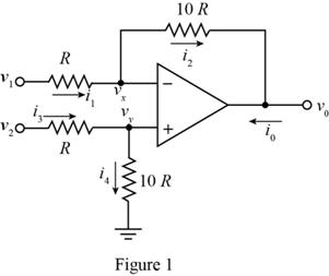
The given diagram is shown in Figure 1
The expression for the value of the voltage
Apply KCL at the node
Substitute
Apply KCL at the node
Substitute
Substitute
The expression for the current
Substitute
Substitute
Substitute
The expression for the current
Substitute
Substitute
Substitute
Substitute
Substitute
Substitute
Substitute
Substitute
Substitute
Conclusion:
Therefore, the value of the voltage
(b)
The value of the voltages
Answer to Problem 9.63P
The value of the voltage
Explanation of Solution
Calculation:
Substitute
Substitute
Substitute
Substitute
Substitute
Substitute
Substitute
Conclusion:
Therefore, the value of the voltage
(c)
The value of the voltages
Answer to Problem 9.63P
The value of the voltage
Explanation of Solution
Calculation:
Substitute
Substitute
Substitute
Substitute
Substitute
Substitute
Substitute
Conclusion:
Therefore, the value of the voltage
Want to see more full solutions like this?
Chapter 9 Solutions
Microelectronics: Circuit Analysis and Design


- Can the expert solve an Integral In detall? ⑥M-1 大 80*10万 1012 es dw 7010 80x10³ ⒸP= 1 Sin (Iwl+1) dw 70x10xarrow_forwardQ1:A) Draw the directional control of DC motor using a relay. Switch controlled by PLC +V Ov (a) Motor OV (b) Motor 10 B) Define the encoder with mention its types. The term encoder is used for a device that provides a digital output as a result of angular or linear displacement. incremental encoder 2 6 absolute encoder 2 10 Q2: A) Suppose that PLC connected to three pushbutton switches as shown in this illustration: 4 2000000 0000 000000 0000 Draw a Ladder Diagram program for PLC to turn the lamp ON when the switch statuses be: Switch A = pressed, Switch B = pressed, Switch C = pressed 1:0 I:0 I:0 0:0 H/HH/H 2 Managemenarrow_forwardExample2:- 8. = e.A nia +2.1 = Find the maximum steady-state power capability of a system consisting of a generator equivalent reactance of 0.4pu connected to an infinite bus through a series reactance of 1.0 p.u. The terminal voltage of the generator is held at1.10 p.u. and the voltage of the infinite bus is 1.0 p.u.arrow_forward
- B) A 60-Hz generator is supplying 60% of P max to an infinite bus through a reactive network. A fault occurs which increases the reactance of the network between the generator internal voltage and the infinite bus by 400%. When the fault is cleared, the maximum power that can be delivered is 80% of the original maximum value. Determine the critical clearing angle for the condition described.arrow_forwardIn the circuit shown, let Vs-9, R₁-8, R2-2, and R3-4. Use Nodal analysis to determine the current lo. In particular find: V2= 10= A The relative tolerance for this problem is 5 %. R₁ V₁ + ww R₂ Vs V₂ 21 x R3arrow_forward1. Choose all nodes that must be included, if any, to construct the supernode for Nodal analysis. OV1, V3 OV1, V2 ○ V2, V3 OV1, V2, V4 OV1, V2, V3 O V2, V3, V4 2. Write KCL equation (Nodal equation) at super-node. Write your expression in terms of node voltages V1, V2, V3 and V4 and of the form (G11 V1+G12 V2+G13 V3+G14 V4 = 11), then enter the corresponding values: At super-node KCL: 1/Q G11 1/0 G12 1/Ω G13 1/Q G14 A 3. Use the above equation, the circuit and and super-node inner expression to calculate V3 and then lo : V3= V 10 = R3 Vst + A V₁ + VS2 V₂ V3 w W R₁ R₂ R4 ww R5 V4 V$3arrow_forward
- Enter the matrix values (numerical) to solve for voltages at nodes v1, and v2, for the circuit shown, using Nodal equations. In the matrix, row 1, and row 2, correspond to node v1, and node v2 current expressions, respectively. Let Is1=14, Is2=7, R₁=5, R₂-8, R3=2, and R4-5. [G11 G12] [Vi₁ The matrix values are shown here: = G21 G22 [V2] [41] [12] {Hint: As discussed in class and to avoid sign errors, assume nodal currents are locally defined at each node (leaving) and use node labeling as indicated in the circuit. } The relative tolerance for this problem is 5%. VI R2 ww Isl 12 NODE v1 G11 G12 RI 1/Q 1/0 A 4= NODE v2 G21- 1/Q G22 1/0 12 W A === www R3 R4 www Use Cramer's rule (matrix), substitution, or any other method to calculate the voltages: v1 = V v2= V Is2arrow_forwardOnly expert should attemptarrow_forwardFor the circuit shown below, let l₁ = 9, 1₂ = 14, 13= 12, R₁ = 3, R₂ = 8, and R3 = 5. Use nodal equations to determine V1, V2 and I, as follows: • Consider Node 1, obtain a nodal equation in terms of V₁ and V₂ voltages. Simplify your equation to the format 1V1 + b,V₂ = c, then enter the corresponding values of coefficients b₁ and c₁ 1. b₁ =( C₁ = • Now consider Node 2, obtain a second nodal equation in terms of V₁ and V2 voltages. Simplify your equation to the format -1V₁+b2V2=c2 then enter the corresponding values of coefficients b₂ and c₂ 2. (b₂ = value.) ,၄၇ = - 3. Use (1) and (2) to determine V₂ = 4. Determine V₁ 5. Determine | = i 12 V₁ R1 20 www R2 ww I The relative tolerance for this problem is 5%. R3 This is not a decimal or integer www i3arrow_forward
- For the circuit shown, let V1 = 19 V, Vs2 = 76 V, R₁ = 9, R2 = 9, and R3 = 7. Use Nodal analysis to determine the voltage V2 and the current lo, choose the closet values: V2- 4.788 10 = ○ 2.28 11.978 17.761 35.522 23.957 -9.146 8.32 10.173 A O-7.435 O-5.783 10.531 V sl ་ ་ ་ ན ་་་ ་ ་ ་ ་ ་ ་ ་ ་ +1 ww R₁ R₂ ww R3 Io +1 VS2arrow_forwardNO AI PLEASEarrow_forwardNO AI PLEASEarrow_forward
 Introductory Circuit Analysis (13th Edition)Electrical EngineeringISBN:9780133923605Author:Robert L. BoylestadPublisher:PEARSON
 Delmar's Standard Textbook Of ElectricityElectrical EngineeringISBN:9781337900348Author:Stephen L. HermanPublisher:Cengage Learning
 Programmable Logic ControllersElectrical EngineeringISBN:9780073373843Author:Frank D. PetruzellaPublisher:McGraw-Hill Education
 Fundamentals of Electric CircuitsElectrical EngineeringISBN:9780078028229Author:Charles K Alexander, Matthew SadikuPublisher:McGraw-Hill Education
 Electric Circuits. (11th Edition)Electrical EngineeringISBN:9780134746968Author:James W. Nilsson, Susan RiedelPublisher:PEARSON
 Engineering ElectromagneticsElectrical EngineeringISBN:9780078028151Author:Hayt, William H. (william Hart), Jr, BUCK, John A.Publisher:Mcgraw-hill Education,