
Concept explainers
Videos
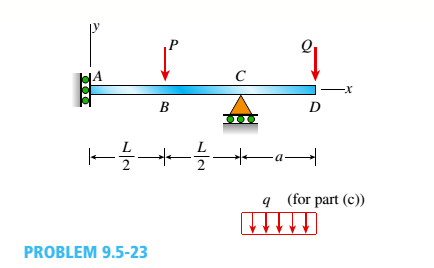
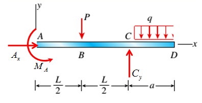
The overhanging beam A BCD supports two concentrated loads P and Q (see figure),
- For what ratio PIQ will the deflection at point B be zero?
- For what ratio will the deflection at point D be zero?
- If Q is replaced by a uniform load with intensity q (on the overhang), repeat parts (a) and (b), but find ratio Pl(qa).
(a)
Ratio P/Q for which deflection at B is zero .
Answer to Problem 9.5.23P
Ratio P/Q for which deflection at B is zero is
Explanation of Solution
Given Information:
The following figure is given along with relevant information,

The deflection at B is zero.
Calculation:
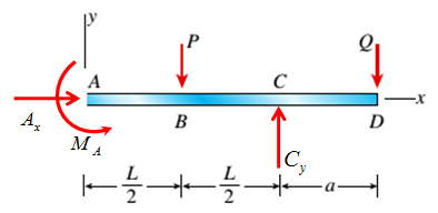
Consider the following free body diagram,
Take equilibrium of forces in horizontal direction as,
Take equilibrium of forces in vertical direction as,
Take equilibrium of moments about A as,
The bending moment at distance x from point A is given by,
The deflection and bending moment is related by following differential equation
Integrate differential equation (1) with respect to x by putting expression for M to get angle of rotations, as,
Integrate angle of rotation with respect to x get deflections as,
The following conditions are used to evaluate integration constants,
Since deflection at B is zero, hence
Now substitute values of constants and solve the above equation to get
Conclusion:
Therefore, the ratio P/Q for which deflection at B is zero is
(b)
Ratio P/Q for which deflection at D is zero .
Answer to Problem 9.5.23P
Ratio P/Q for which deflection at D is zero is
Explanation of Solution
Given Information:
The following figure is given along with relevant information,
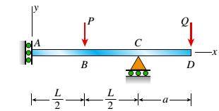
The deflection at D is zero.
Calculation:
Consider the following free body diagram,

Take equilibrium of forces in horizontal direction as,
Take equilibrium of forces in vertical direction as,
Take equilibrium of moments about A as,
The bending moment at distance x from point A is given by,
The deflection and bending moment is related by following differential equation
Integrate differential equation (1) with respect to x by putting expression for M to get angle of rotations, as,
Integrate angle of rotation with respect to x get deflections as,
The following conditions are used to evaluate integration constants,
Since deflection at D is zero, hence
Now substitute values of constants and solve the above equation to get
Conclusion:
Therefore, the ratio P/Q for which deflection at D is zero is
(c)
Ratio P/Q for which deflection at B and D is zero .
Answer to Problem 9.5.23P
Explanation of Solution
Given Information:
The following figure is given along with relevant information,
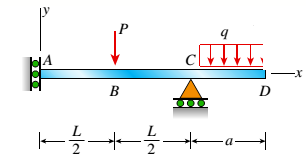
The deflection at B and D is zero.
Calculation:
Consider the following free body diagram,
Take equilibrium of forces in horizontal direction as,
Take equilibrium of forces in vertical direction as,
Take equilibrium of moments about A as,
The bending moment at distance x from point A is given by,
The deflection and bending moment is related by following differential equation
Integrate differential equation (1) with respect to x by putting expression for M to get angle of rotations, as,
Integrate angle of rotation with respect to x get deflections as,
The following conditions are used to evaluate integration constants,
Substitute values of constants to get the expression for deflection.
Since deflection at B is zero, hence
Solve the above equation to get
For deflection at D is zero,
Solve the above equation to get
Conclusion:
Therefore, the ratio P/Q
Want to see more full solutions like this?
Chapter 9 Solutions
Mechanics of Materials (MindTap Course List)


- I REPEAT!!!!! I NEED HANDDRAWING!!!!! NOT A USELESS EXPLANATION!!!! I REPEAT SUBMIT A HANDDRAWING IF YOU CANNOT UNDERSTAND THIS SKIP IT ! I need the real handdrawing complete it by adding these : Pneumatic Valves Each linear actuator must be controlled by a directional control valve (DCV) (e.g., 5/2 or 4/2 valve). The bi-directional motor requires a reversible valve to change rotation direction. Pressure Regulators & Air Supply Include two pressure regulators as per the assignment requirement. Show the main compressed air supply line connecting all components. Limit Switches & Safety Features Attach limit switches to each actuator to detect positions. Implement a two-handed push-button safety system to control actuator movement. Connections Between Components Draw air supply lines linking the compressor, valves, and actuators. Clearly label all inputs and outputs for better understanding.arrow_forwardI need the real handdrawing complete it by adding these : Pneumatic Valves Each linear actuator must be controlled by a directional control valve (DCV) (e.g., 5/2 or 4/2 valve). The bi-directional motor requires a reversible valve to change rotation direction. Pressure Regulators & Air Supply Include two pressure regulators as per the assignment requirement. Show the main compressed air supply line connecting all components. Limit Switches & Safety Features Attach limit switches to each actuator to detect positions. Implement a two-handed push-button safety system to control actuator movement. Connections Between Components Draw air supply lines linking the compressor, valves, and actuators. Clearly label all inputs and outputs for better understanding.arrow_forwardAn elastic bar of the length L and cross section area A is rigidly attached to the ceiling of a room, and it supports a mass M. Due to the acceleration of gravity g the rod deforms vertically. The deformation of the rod is measured by the vertical displacement u(x) governed by the following equations: dx (σ(x)) + b(x) = 0 PDE σ(x) = Edx du Hooke's law (1) b(x) = gp= body force per unit volume where E is the constant Young's modulus, p is the density, and σ(x) the axial stress in the rod. g * I u(x) L 2arrow_forward
- An elastic bar of the length L and cross section area A is rigidly attached to the ceiling of a room, and it supports a mass M. Due to the acceleration of gravity g the rod deforms vertically. The deformation of the rod is measured by the vertical displacement u(x) governed by the following equations: dx (σ(x)) + b(x) = 0 PDE σ(x) = Edx du Hooke's law (1) b(x) = gp= body force per unit volume where E is the constant Young's modulus, p is the density, and σ(x) the axial stress in the rod. g * I u(x) L 2arrow_forwardمتوسعة الفرج بو عمامة المستوى رم الواجب المنزلي رقم 04 تمرین الوان حسب يتمعن العبارات الأتية : A= (+2)+(-45) B=(+13)- C = (+17)-(+13)-(-20)+(-19 D= [(-15)-(+15)]-[(+20) + هست قیم مدرج مبدؤه النقطة ة الطول :tcm A(-2,5): B(+ 2,5) ≤ C (+5) المسافتين : BAD ين الثاني لمستوي مبدؤه 8 وحدتهarrow_forwardPlease do not rely too much on AI, because its answer may be wrong. Please consider it carefully and give your own answer!!!!! You can borrow ideas from AI, but please do not believe its answer.Very very grateful! ( If you write by hand or don't use AI, I'll give you a big thumbs up ) Please do not copy other's work,i will be very very grateful!!Please do not copy other's work,i will be very very grateful!!arrow_forward
- A thin uniform rod of mass m and length 2r rests in a smooth hemispherical bowl of radius r. A moment M = mgr horizontal plane. is applied to the rod. Assume that the bowl is fixed and its rim is in the HINT: It will help you to find the length l of that portion of the rod that remains outside the bowl. M 2r Ꮎ a) How many degrees of freedom does this system have? b) Write an equation for the virtual work in terms of the angle 0 and the motion of the center of mass (TF) c) Derive an equation for the variation in the position of the center of mass (i.e., Sŕƒ) a. HINT: Use the center of the bowl as the coordinate system origin for the problem. d) In the case of no applied moment (i.e., M = 0), derive an equation that can be used to solve for the equilibrium angle of the rod. DO NOT solve the equation e) In the case of an applied moment (i.e., M: = mgr 4 -) derive an equation that can be used to solve for the equilibrium angle of the rod. DO NOT solve the equation. f) Can the angle 0 and…arrow_forwardSolve this problem and show all of the workarrow_forwardSolve this problem and show all of the workarrow_forward
- Solve this problem and show all of the workarrow_forwardPlease do not rely too much on chatgpt, because its answer may be wrong. Please consider it carefully and give your own answer. You can borrow ideas from gpt, but please do not believe its answer.Very very grateful! Please do not copy other's work,i will be very very grateful!!Please do not copy other's work,i will be very very grateful!!arrow_forward= The frame shown is fitted with three 50 cm diameter frictionless pulleys. A force of F = 630 N is applied to the rope at an angle ◊ 43°. Member ABCD is attached to the wall by a fixed support at A. Find the forces indicated below. Note: The rope is tangent to the pully (D) and not secured at the 3 o'clock position. a b •C *су G E e d BY NC SA 2013 Michael Swanbom Values for dimensions on the figure are given in the following table. Note the figure may not be to scale. Variable Value a 81 cm b 50 cm с 59 cm d 155 cm For all answers, take x as positive to the right and positive upward. At point A, the fixed support exerts a force of: A = + ĴN and a reaction couple of: →> ΜΑ Member CG is in Select an answer magnitude У as k N-m. and carries a force of N.arrow_forward
 Mechanics of Materials (MindTap Course List)Mechanical EngineeringISBN:9781337093347Author:Barry J. Goodno, James M. GerePublisher:Cengage Learning