Concept explainers
The tapered cantilever beam AB shown in the figure has a solid circular cross section. The diameters at the ends A and B are dAand dB= 2dA, respectively. Thus, the diameter d and moment of inertia / at distance v from the free end are, respectively,
in which IAis the moment of inertia at end A of the beam.
Determine the equation of the deflection curve and the deflection SAat the free end of the beam due to the load P.
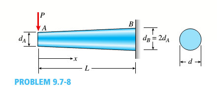
The equation for the deflection curve and the deflection
Answer to Problem 9.7.8P
The equation for the deflection curve and the deflection
Explanation of Solution
Given Information:
We have,
Length of the tapered cantilever beam AB, L
Load at point A as P
Diameter at point A,
Diameter at point B,
Moment of inertia, I
The bending moment is
So, the 2nd degree diffrential equation would be,
In the above equation, taking integration on both sides :
According to boundary condition at x=L,
In above equation taking integration again,
And at 2nd Boundary conditions, x = L and v = 0.
At x = 0, then
At point A, the deflection would be below.
Conclusion:
The answers are calculated according to deflection and deflection curve.
Want to see more full solutions like this?
Chapter 9 Solutions
Mechanics of Materials (MindTap Course List)
- The tapered cantilever beam AB shown in the figure has a thin-walled, hollow circular cross sections of constant thickness t. The diameters at the ends A and B are dAand dB= 2dA, respectively. Thus, the diameter d and moment of inertia / at distance x from the free end are, respectively, in which IAis the moment of inertia at end A of the beam. Determine the equation of the deflection curve and the deflection 8 Aat the free end of the beam due to the load P.arrow_forwardA simple beam ACE is constructed with square cross sections and a double taper (see figure). The depth of the beam at the supports is dAand at the midpoint is dc= 2d 4. Each half of the beam has length L. Thus, the depth and moment of inertia / at distance x from the left-hand end are, respectively, in which IAis the moment of inertia at end A of the beam. (These equations are valid for .x between 0 and L, that is, for the left-hand half of the beam.) Obtain equations for the slope and deflection of the left-hand half of the beam due to the uniform load. From the equations in part (a), obtain formulas for the angle of rotation 94at support A and the deflection Scat the midpoint.arrow_forwardA tapered cantilever beam A B supports a concentrated load P at the free end (see figure). The cross sections of the beam are rectangular with constant width A, depth d Aat support A, and depth ds= ^dJ2 at the support. Thus, the depth d and moment of inertia / at distance x from the free end are, respectively, in which / 4 is the moment of inertia at end A of the beam. Determine the equation of the deflection curve and the deflection S 4at the free end of the beam due to the load P.arrow_forward
- A beam ABC is fixed at end A and supported by beam DE at point B (sec figure). Both beams have the same cross section and are made of the same material. Determine all reactions due to the load P. What is the numerically largest bending moment in cither beam?arrow_forwardTwo identical, simply supported beams AB and CD are placed so that they cross each other at their midpoints (sec figure). Before the uniform load is applied, the beams just touch each other at the crossing point. Determine the maximum bending moments (mab)max* and (MCD)max beams AB and CD, respectively, due to the uniform load if the intensity of the load is q = 6.4 kN/m and the length of each beam is L = 4 m.arrow_forward-22 Derive the equations of the deflection curve for a simple beam AB with a distributed load of peak intensity q0acting over the left-hand half of the span (see figure). Also, determine the deflection cat the midpoint of the beam. Use the second-order differential equation of the deflection curve.arrow_forward
- A beam with a channel section is subjected to a bending moment M having its vector at an angle 0 to the 2 axis (see figure). Determine the orientation of the neutral axis and calculate the maximum tensile stress et and maximum compressive stress ecin the beam. Use the following data: C 8 × 11.5 section, M = 20 kip-in., tan0=l/3. See Table F-3(a) of Appendix F for the dimensions and properties of the channel section.arrow_forwardThe cross section of a rectangular beam having a width b and height h is shown in part a of the figure. For reasons unknown to the beam designer, it is planned to add structural projections of width b/9 and height d/9 the top and bottom of the beam (see part b of the figure). For what values of d is the bending-moment capacity of the beam increased? For what values is it decreased?arrow_forwardA cantilever beam has two triangular loads as shown in the figure. Find an expression for beam deflection Scusing Superposition. Find the required magnitude of load intensity q2in terms of q0so that the deflection at C is zero. Find an expression for the deflection at C if both load intensities, qxand q2, are equal to q0.arrow_forward
- -1 through 5.10-6 A wide-flange beam (see figure) is subjected to a shear force V. Using the dimensions of the cross section, calculate the moment of inertia and then determine the following quantities: The maximum shear stress tinixin the web. The minimum shear stress rmin in the web. The average shear stress raver (obtained by dividing the shear force by the area of the web) and the ratio i^/t^ The shear force carried in the web and the ratio K b/K. Note: Disregard the fillets at the junctions of the web and flanges and determine all quantities, including the moment of inertia, by considering the cross section to consist of three rectangles. 5.10-2 Dimensions of cross section: b = 180 mm, v = 12 mm, h = 420 mm, i = 380 mm, and V = 125 kN.arrow_forward-1 through 5.10-6 A wide-flange beam (see figure) is subjected to a shear force V. Using the dimensions of the cross section, calculate the moment of inertia and then determine the following quantities: The maximum shear stress tinixin the web. The minimum shear stress rmin in the web. The average shear stress raver (obtained by dividing the shear force by the area of the web) and the ratio i^/t^ The shear force carried in the web and the ratio V^tV. Noie: Disregard the fillets at the junctions of the web and flanges and determine all quantities, including the moment of inertia, by considering the cross section to consist of three rectangles. 5.10-3 Wide-flange shape, W 8 x 28 (see Table F-L Appendix F); V = 10 karrow_forward-1 through 5.10-6 A wide-flange beam (see figure) is subjected to a shear force V. Using the dimensions of the cross section, calculate the moment of inertia and then determine the following quantities: The maximum shear stress tinixin the web. The minimum shear stress rmin in the web. The average shear stress raver (obtained by dividing the shear force by the area of the web) and the ratio i^/t^ The shear force carried in the web and the ratio V^tV. Note: Disregard the fillets at the junctions of the web and flanges and determine all quantities, including the moment of inertia, by considering the cross section to consist of three rectangles. 5.10-4 Dimensions of cross section: b = 220 mm, f = 12 mm, h = 600 mm, hx= 570 mm, and V = 200 kN.arrow_forward
- Mechanics of Materials (MindTap Course List)Mechanical EngineeringISBN:9781337093347Author:Barry J. Goodno, James M. GerePublisher:Cengage Learning