
Mechanics of Materials (MindTap Course List)
9th Edition
ISBN: 9781337093347
Author: Barry J. Goodno, James M. Gere
Publisher: Cengage Learning
expand_more
expand_more
format_list_bulleted
Concept explainers
Videos
Textbook Question
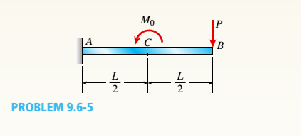
Chapter 9, Problem 9.6.5P
-5 Calen1ate the deflections S 3a nd &c atpoints B and C, respectively, of the cantilever beam ACB shown in the figure. Assume M0= 36 kip-in., P = 3.8 kips, L = 8 ft, and EI = 2.25 X 10* Ib-in2.
Expert Solution & Answer
Want to see the full answer?
Check out a sample textbook solution
Students have asked these similar questions
3. (计算题)
Calculate the DOF of the following mechanism
(a)唧筒机构
5. (计算题)
Calculate the DOF of the following mechanism
D
A
B
E
4.(计算题)
Calculate the DOF of the following mechanism
wwwww
التحفة
www
Chapter 9 Solutions
Mechanics of Materials (MindTap Course List)
Ch. 9 - The equation of the deflection curve for a...Ch. 9 - The equation of the deflection curve for a simply...Ch. 9 - -3 The deflection curve for a simple beam AB (see...Ch. 9 - The deflection curve for a simple beam AB (sec...Ch. 9 - The deflection curve for a cantilever beam AB (sec...Ch. 9 - The deflection curve for a cantilever beam AB (see...Ch. 9 - A simply supported beam is loaded with a point...Ch. 9 - A I-meter-long, simply supported copper beam (E =...Ch. 9 - A wide-flange beam (W 12 x 35) supports a uniform...Ch. 9 - A uniformly loaded, steel wide-flange beam with...
Ch. 9 - What is the span length L of a uniformly loaded,...Ch. 9 - -6 Calculate the maximum deflection of a uniformly...Ch. 9 - A cantilever beam with a uniform load (see figure)...Ch. 9 - A gold-alloy microbeam attached to a silicon wafer...Ch. 9 - Obtain a formula for the ratio c/maxof the...Ch. 9 - A cantilever beam model is often used to represent...Ch. 9 - B cams AB and CDE are connected using rigid link...Ch. 9 - -12 Derive the equation of the deflection curve...Ch. 9 - -13 Derive the equation of the deflection curve...Ch. 9 - -14 A cantilever beam AB supporting a triangularly...Ch. 9 - A cantilever beam has a length L = 12 ft and a...Ch. 9 - A simple beam with an overhang is subjected to d...Ch. 9 - -17 A cantilever beam AB is acted upon by a...Ch. 9 - -18 The beam shown in the figure has a sliding...Ch. 9 - -19 Derive the equations of the deflect ion curve...Ch. 9 - -20 Derive the equations of the deflection curve...Ch. 9 - -21 Derive the equations of the deflection curve...Ch. 9 - -22 Derive the equations of the deflection curve...Ch. 9 - -23 The beam shown in the figure has a sliding...Ch. 9 - -1 Derive the equation of the deflection curve for...Ch. 9 - -2 A simple beam AB is subjected to a distrib uted...Ch. 9 - -3 The simple beam AB shown in the figure has...Ch. 9 - -4 A beam with a uniform load has a sliding...Ch. 9 - -5 The distributed load acting on a cantilever...Ch. 9 - -6 A cantilever beam .4B is subjected to a...Ch. 9 - -7 A beam on simple supports is subjected to a...Ch. 9 - Derive the equation of the deflection curve for...Ch. 9 - -9 Derive the equations of the deflection curve...Ch. 9 - -10 Derive the equations of the deflection curve...Ch. 9 - A simply supported beam (E = 1600 ksi) is loaded...Ch. 9 - A simply supported beam (E = 12 GPa) carries a...Ch. 9 - Copper beam AB has circular cross section with a...Ch. 9 - Beam ABC is loaded by a uniform load q and point...Ch. 9 - A cantilever beam of a length L = 2.5 ft has a...Ch. 9 - A cantilever beam carries a trapezoidal...Ch. 9 - -5-7 A cantilever beam AB carries three equalaly...Ch. 9 - A simple beam AB supports five equally spaced...Ch. 9 - The cantilever beam AB shown in the figure has an...Ch. 9 - Beam ACE hangs from two springs, as shown in the...Ch. 9 - What must be the equation y =f(x) of the axis of...Ch. 9 - -12 Determine the angle of rotation Band...Ch. 9 - The cantilever beam ACE shown in the figure has...Ch. 9 - A cantilever beam is subjected to load P at...Ch. 9 - Use the method of superposition to find the angles...Ch. 9 - Repeat Problem 9,5-15 for the anti-symmetric...Ch. 9 - A cantilever beam is subjected to a quadratic...Ch. 9 - A beam ABCD consisting of a simple span BD and an...Ch. 9 - A horizontal load P acts at end C of the bracket...Ch. 9 - A beam ABC having flexural rigidity EI = 75 kN irT...Ch. 9 - Determine the angle of rotation 0Band deflectionCh. 9 - -22 A simple beam AB supports a uniform load of...Ch. 9 - The overhanging beam A BCD supports two...Ch. 9 - A thin metal strip of total weight W and length L...Ch. 9 - An overhanging beam ABC with flexural rigidity EI...Ch. 9 - A beam A BCD rests on simple supports at B and C...Ch. 9 - The compound beam ABC shown in the figure has a...Ch. 9 - A compound beam ABC DE (see figure) consists of...Ch. 9 - A steel beam ABC is simply supported at A and held...Ch. 9 - -30. Calculate the deflection at point C of a beam...Ch. 9 - Compound beam ABC is loaded by point load P = 1.5...Ch. 9 - The compound beam shown in the figure consists of...Ch. 9 - -33 Find the horizontal deflection hand verti cal...Ch. 9 - The fr a me A BCD shown in the heure is squeezed...Ch. 9 - A framework A BCD is acted on by counterclockwise...Ch. 9 - A framework A BCD is acted on by force P at 2L/3...Ch. 9 - A beam ABCDE has simple supports at B and D and...Ch. 9 - A frame ABC is loaded at point C by a force P...Ch. 9 - The wing of a large commercial jet is represented...Ch. 9 - The wing of a small plane is represented by a...Ch. 9 - Find an expression for required moment MA(in terms...Ch. 9 - Find an expression for required moment MA(in terms...Ch. 9 - Find required distance d (in terms of L) so that...Ch. 9 - A cantilever beam has two triangular loads as...Ch. 9 - -1 A cantilever beam AB is subjected to a uniform...Ch. 9 - The load on a cantilever beam AB has a triangular...Ch. 9 - A cantilever beam AB is subjected to a...Ch. 9 - Determine the angle of rotation BBand the...Ch. 9 - -5 Calen1ate the deflections S 3a ndCh. 9 - A cantileverbeam^Cßsupportstwo concentrated loads...Ch. 9 - Obtain formulas for the angle of rotation 0Aat...Ch. 9 - A simple beam AB supports two concentrated loads P...Ch. 9 - A simple beam AB is subjected to a load in the...Ch. 9 - -10 The simple beam AB shown in the figure...Ch. 9 - A simple beam AB is subjected to couples M0and 2A0...Ch. 9 - The cantilever beam ACB shown in the figure has...Ch. 9 - The cantilever beam ACB shown in the figure...Ch. 9 - Beam ACB hangs from two springs, as shown in the...Ch. 9 - -4 A simple beam ABCD has moment of inertia I near...Ch. 9 - A beam ABC has a rigid segment from A to B and a...Ch. 9 - A simple beam ABC has a moment of inertia 1,5 from...Ch. 9 - The tapered cantilever beam AB shown in the figure...Ch. 9 - The tapered cantilever beam AB shown in the figure...Ch. 9 - A tapered cantilever beam A B supports a...Ch. 9 - A tapered cantilever beam AB supports a...Ch. 9 - Repeat Problem 97-10, but now use the tapered...Ch. 9 - A simple beam ACE is constructed with square cross...Ch. 9 - A uniformly loaded simple beam AB (see figure) of...Ch. 9 - A simple beam AB of length L supports a...Ch. 9 - A propped cantilever beam AB of length L and with...Ch. 9 - A simple beam AB of length L is subjected to loads...Ch. 9 - A beam ABC with simple supports at A and B and an...Ch. 9 - A simple beam ACB supporting a uniform load q over...Ch. 9 - The frame shown in the figure consists of a beam...Ch. 9 - A simple beam AB of length L is loaded at the...Ch. 9 - The simple beam shown in the figure supports a...Ch. 9 - An overhanging beam ABC supports a concentrated...Ch. 9 - The cantilever beam shown in the figure supports a...Ch. 9 - A simple beam ACB supports a uniform load of...Ch. 9 - A cantilever beam ACB supports two concentrated...Ch. 9 - The cantilever beam A CB shown in the hgure is...Ch. 9 - The frame A BC support s a concentrated load P at...Ch. 9 - A simple beam ABC DE supports a uniform load of...Ch. 9 - An overhanging beam ABC is subjected to a couple...Ch. 9 - An overhanging beam ABC rests on a simple support...Ch. 9 - A symmetric beam A BCD with overhangs at both ends...Ch. 9 - A heavy object of weight W is dropped onto the...Ch. 9 - An object of weight Wis dropped onto the midpoint...Ch. 9 - A cantilever beam AB of length L = 6 It is...Ch. 9 - A weight W = 20 kN falls through a height h = 1,0...Ch. 9 - A weight W = 4000 lb falls through a height h =...Ch. 9 - An overhanging beam ABC with a rectangular cross...Ch. 9 - A heavy flywheel rotates at an angular speed m...Ch. 9 - A simple beam AB of length L and height /;...Ch. 9 - A cantilever beam JA of length Land height/; (see...Ch. 9 - An overhanging beam ABC of height h has a sliding...Ch. 9 - A simple beam AB of length L and height h (see...Ch. 9 - Beam AB has an elastic support kR at A, pin...
Knowledge Booster


Learn more about
Need a deep-dive on the concept behind this application? Look no further. Learn more about this topic, mechanical-engineering and related others by exploring similar questions and additional content below.Similar questions
- VIMAarrow_forward1. Calculation Calculate the DOF of the following mechanis m 2 3 1 Please enter the answerarrow_forwarda) Determine state of stress at all points (a, b and c). These points are located on the exteriorsurface of the beam. Point a is located along the centreline of the beam, point b is 15mmfrom the centreline and point c is located on the edge of the beam. Present yourresults in a table and ensure that your sign convention is clearly shownb) Construct Mohrs circle at this point andcalculate the principal stresses and maximum in‐plane shear stress (τmax) at pointc. sketch the resulting state of stress at this point clearly indicating themagnitude of the stresses and any angles associated with the state of stress (principal ormaximum in‐plane shear).arrow_forward
- parts e,f,garrow_forwardFigure 9-6 9-49 An aluminum alloy plate with dimensions 20 cm x 10 cm × 2 cm needs to be cast with a secondary dendrite arm spacing of 10-2 cm (refer to Figure 9-6). What mold constant B is required (assume n = 2 )? Secondary dendrite arm spacing (cm) - 10-1 10-2 10-3 10 41 0.1 1 Copper Zinc alloys Aluminum alloys 10 100 1,000 10,000 100,000 Solidification time (s)arrow_forward9-72 Figure 9-29 shows a cylindrical riser attached to a casting. Compare the solidification times for each casting section and the riser and determine whether the riser will be effective. Figure 9-29 Т 3 6 3 8 3 6 Details A diagram shows the step-block casting. A cylinder of height "7" and diameter "3" is kept on a platform consisting of 2 steps. The width of the second step of the platform is labeled as "3". The horizontal length of the first step is labeled as "6." The horizontal length, width and height of the first step are labeled "6", "8" and "3".arrow_forward
- 6/94 Determine the minimum coefficient of static friction for which the bar can be in static equilibrium in the config- uration shown. The bar is uniform and the fixed peg at C is small. Neglect friction at B. A L PROBLEM 6/94 B L 22arrow_forwardQ2. For the following situation, estimate the minimum required compressive strength of 20/40 proppant. If intermediate-strength proppant is used, estimate the permeability of the proppant pack: Formation depth: 10,000 ft Overburden density: 165lbm/ft3 Poison’s ratio: 0.25 Biot constant: 0.7 Reservoir pressure: 6,500 psi Production drawdown: 2,000 and 4,000 psiarrow_forwardA 3-in.-radius drum is rigidly attached to a 5-in.-radius drum as shown. One of the drums rolls without sliding on the surface shown, and a cord is wound around the other drum. Knowing that at the instant shown. point A has a velocity of 4.875 in./sin./s and an acceleration of 15.50 in./s2in./s2 , both directed to the right, determine the accelerations of points A, B, and C of the drums. The cord is wound around the 3 inch radius drum. Point B is at the bottom of the 5 inch radius drum. Point A is at the bottom of the 3 inch radius drum. Point C is on the right edge of the 5 inch radius drum. The accelerations of point B is______ in./s2 . The accelerations of point A is ______ in./s2 ______ ⦨ °. at what angle/direction The accelerations of point C is______ in./s2 ______ ⦪ °. at what angle/direction?arrow_forward
- A total volume of mud is 1,000 bbls that has a mud weight of 9.1 ppg. Calculate the volumefractions of water, Bentonite, and the weight of Bentonite used. Density of powder Bentonite is 156 lbm/ft3arrow_forwardA 3-in.-radius drum is rigidly attached to a 5-in.-radius drum as shown. One of the drums rolls without sliding on the surface shown, and a cord is wound around the other drum. Knowing that at the instant shown. point A has a velocity of 4.875 in./sin./s and an acceleration of 15.50 in./s2in./s2 , both directed to the right, determine the accelerations of points A, B, and C of the drums. The cord is wound around the 3 inch radius drum. Point B is at the bottom of the 5 inch radius drum. Point A is at the bottom of the 3 inch radius drum. Point C is on the right edge of the 5 inch radius drum. The accelerations of point B is ______ in./s2 The accelerations of point A is ______ in./s2 _____⦨ °. The accelerations of point C is _______ in./s2 ____ ⦪ °.arrow_forwardThe average heat transfer coefficent for airflow over an odd shaped body is to be determined by mass transfer measurements and using the Chilton-Colburn analogy btwn heat and mass transfer. The experiemnt is conducted by blowing dry air at 1 atm at a free-stream velocity of 2 m/s over a body covered with a layer of naphthalene. The surface area of the body is .75 m^2, and it is observed that 100 g of maphthalene has sublimated in 45 min. During the experiemnt, both the body and the air were kep at 25oC, at which the vapor pressure and mass diffusivity of naphthalene are 11 Pa and Dab=0.61*10^-5 m^2/s respectively. Determine the heat transfer coefficent under the same flow conditions over the same geometry.arrow_forward
arrow_back_ios
SEE MORE QUESTIONS
arrow_forward_ios
Recommended textbooks for you
 Mechanics of Materials (MindTap Course List)Mechanical EngineeringISBN:9781337093347Author:Barry J. Goodno, James M. GerePublisher:Cengage Learning
Mechanics of Materials (MindTap Course List)
Mechanical Engineering
ISBN:9781337093347
Author:Barry J. Goodno, James M. Gere
Publisher:Cengage Learning
Solids: Lesson 53 - Slope and Deflection of Beams Intro; Author: Jeff Hanson;https://www.youtube.com/watch?v=I7lTq68JRmY;License: Standard YouTube License, CC-BY