
Mechanics of Materials
9th Edition
ISBN: 9780133254426
Author: Russell C. Hibbeler
Publisher: Prentice Hall
expand_more
expand_more
format_list_bulleted
Concept explainers
Videos
Textbook Question
Chapter 8.1, Problem 8.4P
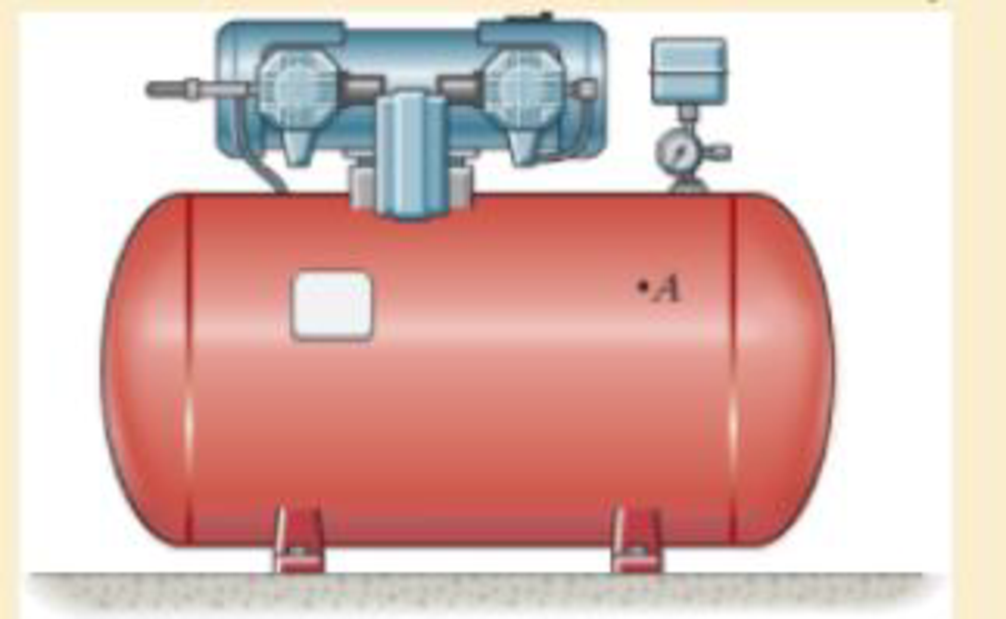
If the inner diameter of the tank is 22 in., and the wall thickness is 0.25 in., determine the stress components acting at point A. Draw a volume element of the material at this point, and show the results on the element.
Expert Solution & Answer
Want to see the full answer?
Check out a sample textbook solution
Students have asked these similar questions
7. A motor shaft rotating at 1440 r.p.m. has to transmit 15 kW to a low speed shaft rotating at 500 r.p.m.
The teeth are 20° involute with 25 teeth on the pinion. Both the pinion and gear are made of cast iron
with a maximum safe stress of 56 MPa. A safe stress of 35 MPa may be taken for the shaft on which
the gear is mounted. Design and sketch the spur gear drive to suit the above conditions. The starting
torque may be assumed as 1,25 times the running torque.
Ruins 20 LW at 100 nm to another shaft running approxi
6.
A two stage reduction drive is to be designed to transmit 2 kW; the input speed being 960 r.p.m. and
overall reduction ratio being 9. The drive consists of straight tooth spur gears only, the shafts being
spaced 200 mm apart, the input and output shafts being co-axial.
2 A metal block of mass m = 10 kg is sliding along a frictionless surface with an initial speed
Vo, as indicated below. The block then slides above an electromagnetic brake that applies a
force FEB to the block, opposing its motion. The magnitude of the electromagnetic force
varies quadratically with the distance moved along the brake (x):
10
FEB = kx²,
with k
= 5
N
m²
V₁ = 8 m/s
m = 10 kg
FEB
Frictionless surface
Electromagnetic brake
⇒x
Determine how far the block slides along the electromagnetic brake before stopping, in m.
Chapter 8 Solutions
Mechanics of Materials
Ch. 8.1 - If it is subjected to an internal pressure of p =...Ch. 8.1 - If it is subjected to an internal pressure of p =...Ch. 8.1 - The thin-walled cylinder can be supported in one...Ch. 8.1 - If the inner diameter of the tank is 22 in., and...Ch. 8.1 - Prob. 8.5PCh. 8.1 - 8–6. If the flow of water within the pipe in Prob....Ch. 8.1 - A boiler is constructed of 8-mm-thick steel plates...Ch. 8.1 - 88. The steel water pipe has an inner diameter of...Ch. 8.1 - The steel water pipe has an inner diameter of 12...Ch. 8.1 - The A-36-steel band is 2 in. wide and is secured...
Ch. 8.1 - Two hemispheres having an inner radius of 2 ft and...Ch. 8.1 - A pressure-vessel head is fabricated by welding...Ch. 8.1 - An A-36-steel hoop has an inner diameter of 23.99...Ch. 8.1 - The ring, having the dimensions shown, is placed...Ch. 8.1 - The inner ring A has an inner radius r1 and outer...Ch. 8.1 - *8–16. A closed-ended pressure vessel is...Ch. 8.1 - In order to increase the strength of the pressure...Ch. 8.2 - Show the results on the left segment.Ch. 8.2 - Show the stress that each of these loads produce...Ch. 8.2 - Fundamental Problems F81. Determine the normal...Ch. 8.2 - Show the results in a differential element at the...Ch. 8.2 - Determine the state of stress at point A on the...Ch. 8.2 - Determine the magnitude of the load P that will...Ch. 8.2 - Determine the state of stress at point B. Show the...Ch. 8.2 - Determine the state of stress at point A on the...Ch. 8.2 - Determine the state of stress at point A on the...Ch. 8.2 - Show the results in a differential element at the...Ch. 8.2 - Determine the shortest distance d to the edge of...Ch. 8.2 - 8–19. Determine the maximum and minimum normal...Ch. 8.2 - *8–20. Determine the maximum and minimum normal...Ch. 8.2 - Also, plot the normal-stress distribution over the...Ch. 8.2 - 8–22. The clamp is made from members AB and AC,...Ch. 8.2 - 8–23. The clamp is made from members AB and AC,...Ch. 8.2 - Prob. 8.24PCh. 8.2 - 8–25. The bearing pin supports the load of 700 lb....Ch. 8.2 - Determine the maximum normal stress on the cross...Ch. 8.2 - If the wood has an allowable normal stress of...Ch. 8.2 - *8–28. The cylindrical post, having a diameter of...Ch. 8.2 - 8–29. Determine the maximum load P that can be...Ch. 8.2 - If the force of 100 N is applied to the handles,...Ch. 8.2 - 8–31. Determine the smallest distance d to the...Ch. 8.2 - *8–32. The horizontal force of P = 80 kN acts at...Ch. 8.2 - 8–33. The control lever is subjected to a...Ch. 8.2 - 8–34. The control lever is subjected to a...Ch. 8.2 - 8–35. The tubular shaft of the soil auger is...Ch. 8.2 - Determine the state of stress at point A on the...Ch. 8.2 - Determine the state of stress at point B on the...Ch. 8.2 - Determine the state of stress acting at point D....Ch. 8.2 - Determine the state of stress acting at point E....Ch. 8.2 - Prob. 8.40PCh. 8.2 - Prob. 8.41PCh. 8.2 - 8–42. Determine the state of stress at point A on...Ch. 8.2 - 8–43. Determine the state of stress at point B on...Ch. 8.2 - Neglect the weight of the block.Ch. 8.2 - Neglect the weight of the block.Ch. 8.2 - Prob. 8.46PCh. 8.2 - Prob. 8.47PCh. 8.2 - Prob. 8.48PCh. 8.2 - Prob. 8.49PCh. 8.2 - The coiled spring is subjected to a force P. If we...Ch. 8.2 - Specify the region to which this load can be...Ch. 8.2 - Determine the smallest force P that can be applied...Ch. 8.2 - 8–53. The 1-in.-diameter rod is subjected to the...Ch. 8.2 - 8–54. The 1-in.-diameter rod is subjected to the...Ch. 8.2 - 8–55. Determine the state of stress at point A on...Ch. 8.2 - *8–56. Determine the state of stress at point B on...Ch. 8.2 - Determine the stress components at points A and B...Ch. 8.2 - Determine the stress components at points C and D...Ch. 8.2 - 8–59. If P = 60 kN, determine the maximum normal...Ch. 8.2 - *8–60. Determine the maximum allowable force P, if...Ch. 8.2 - If the force at the ram on the clamp at D is P= 8...Ch. 8.2 - Determine the maximum ram force P that can be...Ch. 8.2 - and an outer radius of 3.00 in. If the face of the...Ch. 8.2 - for points E and F.Ch. 8.2 - 8–65. Determine the state of stress at point A on...Ch. 8.2 - 8–66. Determine the state of stress at point B on...Ch. 8.2 - 8–67. The metal link is subjected to the axial...Ch. 8.2 - *8–68. The bar has a diameter of 40 mm. If it is...Ch. 8.2 - 8–69. Solve Prob. 8-68 for point B.
Ch. 8.2 - Determine the stress components at point A. Sketch...Ch. 8.2 - for the stress components at point B.Ch. 8.2 - Determine the state of stress at point A at...Ch. 8.2 - Determine the state of stress at point B at...Ch. 8 - If it supports a cable loading of 800 lb,...Ch. 8 - Determine the state of stress at point E on the...Ch. 8 - Determine the state of stress at point F on the...Ch. 8 - If it has a mass of 5 kg/m, determine the largest...Ch. 8 - 8–78. Solve Prob. 8–77 if the bar has a circular...Ch. 8 - The suspender arm AE has a square cross-sectional...Ch. 8 - Prob. 8.80RPCh. 8 - 8–81. The hydraulic cylinder has an inner diameter...Ch. 8 - If the cross section of the femur at section aa...Ch. 8 - 8-83. Air pressure in the cylinder is increased by...Ch. 8 - *8-84. Determine the maximum force P that can be...Ch. 8 - and is used to support the vertical reactions of...Ch. 8 - and is used to support the vertical reactions of...
Knowledge Booster


Learn more about
Need a deep-dive on the concept behind this application? Look no further. Learn more about this topic, mechanical-engineering and related others by exploring similar questions and additional content below.Similar questions
- Q1: Determine the length, angle of contact, and width of a 9.75 mm thick leather belt required to transmit 15 kW from a motor running at 900 r.p.m. The diameter of the driving pulley of the motor is 300 mm. The driven pulley runs at 300 r.p.m. and the distance between the centers of two pulleys is 3 meters. The density of the leather is 1000 kg/m³. The maximum allowable stress in the leather is 2.5 MPa. The coefficient of friction between the leather and pulley is 0.3. Assume open belt drive.arrow_forward5. A 15 kW and 1200 r.p.m. motor drives a compressor at 300 r.p.m. through a pair of spur gears having 20° stub teeth. The centre to centre distance between the shafts is 400 mm. The motor pinion is made of forged steel having an allowable static stress as 210 MPa, while the gear is made of cast steel having allowable static stress as 140 MPa. Assuming that the drive operates 8 to 10 hours per day under light shock conditions, find from the standpoint of strength, 1. Module; 2. Face width and 3. Number of teeth and pitch circle diameter of each gear. Check the gears thus designed from the consideration of wear. The surface endurance limit may be taken as 700 MPa. [Ans. m = 6 mm; b= 60 mm; Tp=24; T=96; Dp = 144mm; DG = 576 mm]arrow_forward4. G A micarta pinion rotating at 1200 r.p.m. is to transmit 1 kW to a cast iron gear at a speed of 192 r.p.m. Assuming a starting overload of 20% and using 20° full depth involute teeth, determine the module, number of teeth on the pinion and gear and face width. Take allowable static strength for micarta as 40 MPa and for cast iron as 53 MPa. Check the pair in wear.arrow_forward
- I want to solve these choicesarrow_forward2. A spur gear made of bronze drives a mid steel pinion with angular velocity ratio of 32: 1. The pressure angle is 14½. It transmits 5 kW at 1800 r.p.m. of pinion. Considering only strength, design the smallest diameter gears and find also necessary face width. The number of teeth should not be less than 15 teeth on either gear. The elastic strength of bronze may be taken as 84 MPa and of steel as 105 MPa. Lewis factor for 14½½ pressure angle may be taken 0.684 0.124 y = No. of teeth as [Ans. m 3 mm; b= 35 mm; Dp = 48 mm; D= 168 mm]arrow_forwardQ2. Determine the safety factors for the bracket rod shown in Figure 2 based on both the distortion-energy theory and the maximum shear theory and compare them. Given: The material is 2024-T4 aluminum with a yield strength of 47 000 psi. The rod length /= 6 in. and arm a = 8 in. The rod outside diameter od 1.5 in., id = 1 in, h=2 in., t=0.5 in., Load F= 1000 lb. Assumptions: The load is static and the assembly is at room temperature. Consider shear due to transverse loading as well as other stresses. (Note: solve in SI units) wall tube Figure 2 armarrow_forward
- The question has been set up with all the cuts needed to accurately derive expressions for V(x) and M(x). Using the cuts free body diagrams set up below, derive expressions for V(x) and M(x). If you use the method of cuts then validate your answers using calculus or vice versa.arrow_forwardIt is required to treat 130 kmol/hr of chloroform-air feed gas mixture that contains 12% chloroform. It is required to remove 93% of chloroform using 150 kmol/hr of solvent that contains 99.6% water and 0.4% chloroform. The cross sectional area of the column is 0.8 m². Calculate the column height using the following data; kx'.a = 1.35 (kmol/m³.s (Ax)), and ky'.a = 0.06 (kmol/m³.s (Ay)), kx/ky = 1.35, and the equilibrium data are: X 0 0.0133 0.033 y 0 0.01 0.0266 0.049 0.064 0.0747 0.0933 0.1053 0.0433 0.06 0.0733 0.111 0.1 0.12 0.14arrow_forward४ B: Find the numerical solution for the 2D equation below and calculate the temperature values for each grid point shown in Fig. 2 (show all steps). (Do only one trail using following initial values and show the final matrix) [T1] T₂ T3 [T] 1 = [0] 0 0 d dx dx) (ka)+4(ka) = dy -20xy, k = 1 + 0.3 T ge L=3cm, 4x= Ay B.Cs.: at x=0=LT=0°C at y=0-L T=10°C Fig. (2)arrow_forward
- : +0 العنوان use only Two rods fins) having same dimensions, one made orass (k = 85 Wm K) and the mer of copper (k = 375 W/m K), having of their ends inserted into a furna. At a section 10.5 cm a way from furnace, the temperature of brass rod 120 Find the distance at which the ame temperature would be reached in the per rod ? both ends are ex osed to the same environment. ns 2.05 ۲/۱ ostrararrow_forwardFor the beam show below, draw A.F.D, S.F.D, B.M.D 6 kN/m 1 M B. 3 M Marrow_forward1. Two long rods of the same diameter-one made of brass (k=85w/m.k) and the other made of copper (k=375 w/m.k) have one of their ends inserted into a furnace (as shown in the following figure). Both rods are exposed to the same environment. At a distance of 105 mm from the furnace, the temperature of the brass rod is 120°C. At what distance from the furnace will the same temperature be reached in the copper rod? Furnace 105 mm T₁ Brass rod ⑪ h Too- x2- Ti Copper rodarrow_forward
arrow_back_ios
SEE MORE QUESTIONS
arrow_forward_ios
Recommended textbooks for you
 Elements Of ElectromagneticsMechanical EngineeringISBN:9780190698614Author:Sadiku, Matthew N. O.Publisher:Oxford University Press
 Mechanics of Materials (10th Edition)Mechanical EngineeringISBN:9780134319650Author:Russell C. HibbelerPublisher:PEARSON
 Thermodynamics: An Engineering ApproachMechanical EngineeringISBN:9781259822674Author:Yunus A. Cengel Dr., Michael A. BolesPublisher:McGraw-Hill Education
 Control Systems EngineeringMechanical EngineeringISBN:9781118170519Author:Norman S. NisePublisher:WILEY
 Mechanics of Materials (MindTap Course List)Mechanical EngineeringISBN:9781337093347Author:Barry J. Goodno, James M. GerePublisher:Cengage Learning
 Engineering Mechanics: StaticsMechanical EngineeringISBN:9781118807330Author:James L. Meriam, L. G. Kraige, J. N. BoltonPublisher:WILEY
Elements Of Electromagnetics
Mechanical Engineering
ISBN:9780190698614
Author:Sadiku, Matthew N. O.
Publisher:Oxford University Press
Mechanics of Materials (10th Edition)
Mechanical Engineering
ISBN:9780134319650
Author:Russell C. Hibbeler
Publisher:PEARSON
Thermodynamics: An Engineering Approach
Mechanical Engineering
ISBN:9781259822674
Author:Yunus A. Cengel Dr., Michael A. Boles
Publisher:McGraw-Hill Education
Control Systems Engineering
Mechanical Engineering
ISBN:9781118170519
Author:Norman S. Nise
Publisher:WILEY
Mechanics of Materials (MindTap Course List)
Mechanical Engineering
ISBN:9781337093347
Author:Barry J. Goodno, James M. Gere
Publisher:Cengage Learning
Engineering Mechanics: Statics
Mechanical Engineering
ISBN:9781118807330
Author:James L. Meriam, L. G. Kraige, J. N. Bolton
Publisher:WILEY
Pressure Vessels Introduction; Author: Engineering and Design Solutions;https://www.youtube.com/watch?v=Z1J97IpFc2k;License: Standard youtube license