
Mechanics of Materials
9th Edition
ISBN: 9780133254426
Author: Russell C. Hibbeler
Publisher: Prentice Hall
expand_more
expand_more
format_list_bulleted
Concept explainers
Videos
Textbook Question
Chapter 8.2, Problem 8.44P
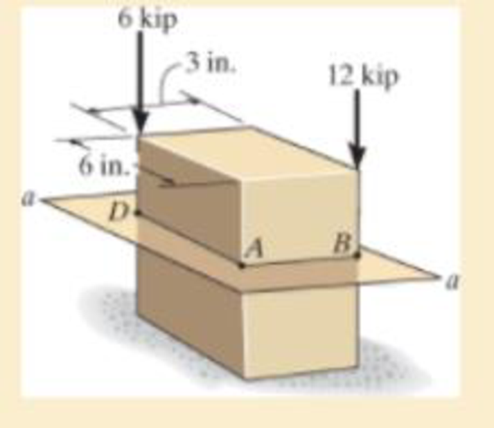
Neglect the weight of the block.
Expert Solution & Answer
Want to see the full answer?
Check out a sample textbook solution
Students have asked these similar questions
from this problem a want you to help to draw the shear moment and the bending moment
reaction at a is 1.6 wL (pos)
handwritten solutions only please. correct answers upvoted
1
8
4
Add numbers so that the sum of any
row or column equals .30 Use only
these numbers:
.1.2.3.4.5.6.10.11.12.12.13.14.14
Chapter 8 Solutions
Mechanics of Materials
Ch. 8.1 - If it is subjected to an internal pressure of p =...Ch. 8.1 - If it is subjected to an internal pressure of p =...Ch. 8.1 - The thin-walled cylinder can be supported in one...Ch. 8.1 - If the inner diameter of the tank is 22 in., and...Ch. 8.1 - Prob. 8.5PCh. 8.1 - 8–6. If the flow of water within the pipe in Prob....Ch. 8.1 - A boiler is constructed of 8-mm-thick steel plates...Ch. 8.1 - 88. The steel water pipe has an inner diameter of...Ch. 8.1 - The steel water pipe has an inner diameter of 12...Ch. 8.1 - The A-36-steel band is 2 in. wide and is secured...
Ch. 8.1 - Two hemispheres having an inner radius of 2 ft and...Ch. 8.1 - A pressure-vessel head is fabricated by welding...Ch. 8.1 - An A-36-steel hoop has an inner diameter of 23.99...Ch. 8.1 - The ring, having the dimensions shown, is placed...Ch. 8.1 - The inner ring A has an inner radius r1 and outer...Ch. 8.1 - *8–16. A closed-ended pressure vessel is...Ch. 8.1 - In order to increase the strength of the pressure...Ch. 8.2 - Show the results on the left segment.Ch. 8.2 - Show the stress that each of these loads produce...Ch. 8.2 - Fundamental Problems F81. Determine the normal...Ch. 8.2 - Show the results in a differential element at the...Ch. 8.2 - Determine the state of stress at point A on the...Ch. 8.2 - Determine the magnitude of the load P that will...Ch. 8.2 - Determine the state of stress at point B. Show the...Ch. 8.2 - Determine the state of stress at point A on the...Ch. 8.2 - Determine the state of stress at point A on the...Ch. 8.2 - Show the results in a differential element at the...Ch. 8.2 - Determine the shortest distance d to the edge of...Ch. 8.2 - 8–19. Determine the maximum and minimum normal...Ch. 8.2 - *8–20. Determine the maximum and minimum normal...Ch. 8.2 - Also, plot the normal-stress distribution over the...Ch. 8.2 - 8–22. The clamp is made from members AB and AC,...Ch. 8.2 - 8–23. The clamp is made from members AB and AC,...Ch. 8.2 - Prob. 8.24PCh. 8.2 - 8–25. The bearing pin supports the load of 700 lb....Ch. 8.2 - Determine the maximum normal stress on the cross...Ch. 8.2 - If the wood has an allowable normal stress of...Ch. 8.2 - *8–28. The cylindrical post, having a diameter of...Ch. 8.2 - 8–29. Determine the maximum load P that can be...Ch. 8.2 - If the force of 100 N is applied to the handles,...Ch. 8.2 - 8–31. Determine the smallest distance d to the...Ch. 8.2 - *8–32. The horizontal force of P = 80 kN acts at...Ch. 8.2 - 8–33. The control lever is subjected to a...Ch. 8.2 - 8–34. The control lever is subjected to a...Ch. 8.2 - 8–35. The tubular shaft of the soil auger is...Ch. 8.2 - Determine the state of stress at point A on the...Ch. 8.2 - Determine the state of stress at point B on the...Ch. 8.2 - Determine the state of stress acting at point D....Ch. 8.2 - Determine the state of stress acting at point E....Ch. 8.2 - Prob. 8.40PCh. 8.2 - Prob. 8.41PCh. 8.2 - 8–42. Determine the state of stress at point A on...Ch. 8.2 - 8–43. Determine the state of stress at point B on...Ch. 8.2 - Neglect the weight of the block.Ch. 8.2 - Neglect the weight of the block.Ch. 8.2 - Prob. 8.46PCh. 8.2 - Prob. 8.47PCh. 8.2 - Prob. 8.48PCh. 8.2 - Prob. 8.49PCh. 8.2 - The coiled spring is subjected to a force P. If we...Ch. 8.2 - Specify the region to which this load can be...Ch. 8.2 - Determine the smallest force P that can be applied...Ch. 8.2 - 8–53. The 1-in.-diameter rod is subjected to the...Ch. 8.2 - 8–54. The 1-in.-diameter rod is subjected to the...Ch. 8.2 - 8–55. Determine the state of stress at point A on...Ch. 8.2 - *8–56. Determine the state of stress at point B on...Ch. 8.2 - Determine the stress components at points A and B...Ch. 8.2 - Determine the stress components at points C and D...Ch. 8.2 - 8–59. If P = 60 kN, determine the maximum normal...Ch. 8.2 - *8–60. Determine the maximum allowable force P, if...Ch. 8.2 - If the force at the ram on the clamp at D is P= 8...Ch. 8.2 - Determine the maximum ram force P that can be...Ch. 8.2 - and an outer radius of 3.00 in. If the face of the...Ch. 8.2 - for points E and F.Ch. 8.2 - 8–65. Determine the state of stress at point A on...Ch. 8.2 - 8–66. Determine the state of stress at point B on...Ch. 8.2 - 8–67. The metal link is subjected to the axial...Ch. 8.2 - *8–68. The bar has a diameter of 40 mm. If it is...Ch. 8.2 - 8–69. Solve Prob. 8-68 for point B.
Ch. 8.2 - Determine the stress components at point A. Sketch...Ch. 8.2 - for the stress components at point B.Ch. 8.2 - Determine the state of stress at point A at...Ch. 8.2 - Determine the state of stress at point B at...Ch. 8 - If it supports a cable loading of 800 lb,...Ch. 8 - Determine the state of stress at point E on the...Ch. 8 - Determine the state of stress at point F on the...Ch. 8 - If it has a mass of 5 kg/m, determine the largest...Ch. 8 - 8–78. Solve Prob. 8–77 if the bar has a circular...Ch. 8 - The suspender arm AE has a square cross-sectional...Ch. 8 - Prob. 8.80RPCh. 8 - 8–81. The hydraulic cylinder has an inner diameter...Ch. 8 - If the cross section of the femur at section aa...Ch. 8 - 8-83. Air pressure in the cylinder is increased by...Ch. 8 - *8-84. Determine the maximum force P that can be...Ch. 8 - and is used to support the vertical reactions of...Ch. 8 - and is used to support the vertical reactions of...
Knowledge Booster


Learn more about
Need a deep-dive on the concept behind this application? Look no further. Learn more about this topic, mechanical-engineering and related others by exploring similar questions and additional content below.Similar questions
- Uppgift 2 (9p) I77777 20 kN 10 kN/m 4 [m] 2 2 Bestäm tvärkrafts- och momentdiagram för balken i figuren ovan. Extrempunkter ska anges med både läge och värde i diagrammen.arrow_forward**Problem 8-45.** The man has a mass of 60 kg and the crate has a mass of 100 kg. If the coefficient of static friction between his shoes and the ground is \( \mu_s = 0.4 \) and between the crate and the ground is \( \mu_c = 0.3 \), determine if the man is able to move the crate using the rope-and-pulley system shown. **Diagram Explanation:** The diagram illustrates a scenario where a man is attempting to pull a crate using a rope-and-pulley system. The setup is as follows: - **Crate (C):** Positioned on the ground with a rope attached. - **Rope:** Connects the crate to a pulley system and extends to the man. - **Pulley on Tree:** The rope runs over a pulley mounted on a tree which redirects the rope. - **Angles:** - The rope between the crate and tree forms a \(30^\circ\) angle with the horizontal. - The rope between the tree and the man makes a \(45^\circ\) angle with the horizontal. - **Man (A):** Pulling on the rope with the intention of moving the crate. This arrangement tests the…arrow_forwardplease solve this problems follow what the question are asking to do please show me step by steparrow_forward
- please help me to solve this problem and determine the stress for each point i like to be explained step by step with the correct answerarrow_forwardplease solve this problem for me the best way that you can explained to solve please show me the step how to solvearrow_forwardplese solbe this problem and give the correct answer solve step by step find the forces and line actionarrow_forward
- please help me to solve this problems first write the line of action and them find the forces {fx=0: fy=0: mz=0: and them draw the shear and bending moment diagram. please explain step by steparrow_forwardplease solve this problem step by step like human and give correct answer step by steparrow_forwardPROBLEM 11: Determine the force, P, that must be exerted on the handles of the bolt cutter. (A) 7.5 N (B) 30.0 N (C) 52.5 N (D) 300 N (E) 325 N .B X 3 cm E 40 cm cm F = 1000 N 10 cm 3 cm boltarrow_forward
arrow_back_ios
SEE MORE QUESTIONS
arrow_forward_ios
Recommended textbooks for you
 Refrigeration and Air Conditioning Technology (Mi...Mechanical EngineeringISBN:9781305578296Author:John Tomczyk, Eugene Silberstein, Bill Whitman, Bill JohnsonPublisher:Cengage Learning
 Precision Machining Technology (MindTap Course Li...Mechanical EngineeringISBN:9781285444543Author:Peter J. Hoffman, Eric S. Hopewell, Brian JanesPublisher:Cengage Learning
Refrigeration and Air Conditioning Technology (Mi...
Mechanical Engineering
ISBN:9781305578296
Author:John Tomczyk, Eugene Silberstein, Bill Whitman, Bill Johnson
Publisher:Cengage Learning
Precision Machining Technology (MindTap Course Li...
Mechanical Engineering
ISBN:9781285444543
Author:Peter J. Hoffman, Eric S. Hopewell, Brian Janes
Publisher:Cengage Learning
Introduction To Engg Mechanics - Newton's Laws of motion - Kinetics - Kinematics; Author: EzEd Channel;https://www.youtube.com/watch?v=ksmsp9OzAsI;License: Standard YouTube License, CC-BY