
Mechanics of Materials
9th Edition
ISBN: 9780133254426
Author: Russell C. Hibbeler
Publisher: Prentice Hall
expand_more
expand_more
format_list_bulleted
Concept explainers
Videos
Textbook Question
Chapter 8.2, Problem 8.45P
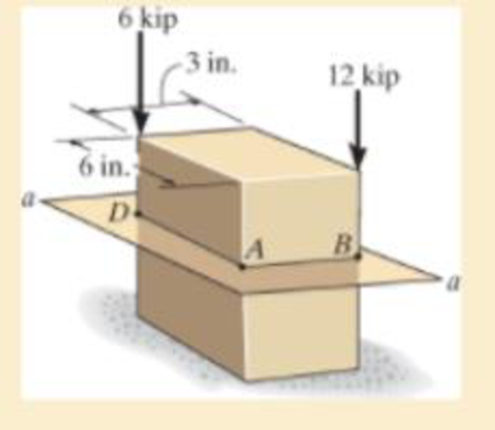
Neglect the weight of the block.
Expert Solution & Answer
Want to see the full answer?
Check out a sample textbook solution
Students have asked these similar questions
A turbocharged engine with a compression ratio of 8 is being designed using an
air standard cycle. The ambient air is assumed to be 300K and 100 kPa. The
temperature at the end of the compression in the cylinder is desired to be 1000K,
assuming no combustion prior to reaching TDC. At the end of the cylinder
expansion the temperature is also desired to be 1000K. If both the turbine and
the compressor have mechanical efficiencies of 80%, what will be the pressure
ratio of the compressor and what will be the turbine exhaust temperature?
Q6: A turbocharged engine with a compression ratio of 8 is being designed using an
air standard cycle. The ambient air is assumed to be 300K and 100 kPa. The
temperature at the end of the compression in the cylinder is desired to be 1000K,
assuming no combustion prior to reaching TDC. At the end of the cylinder
expansion the temperature is also desired to be 1000K. If both the turbine and
the compressor have mechanical efficiencies of 80%, what will be the pressure
ratio of the compressor and what will be the turbine exhaust temperature?
Q5: A 5.6 litre V8 engine with a compression ratio of 9.4:1 operates on an air-standard
Otto cycle at 2800 RPM, with a volumetric efficiency of 90 % and a stoichiometric
air-fuel ratio using gasoline. The exhaust flow undergoes a temperature drop of
44ºC as it passes through the turbine of the supercharger. Calculate (a) mass flow
rate of exhaust gas and (b) power available to drive the turbocharger compressor.
Chapter 8 Solutions
Mechanics of Materials
Ch. 8.1 - If it is subjected to an internal pressure of p =...Ch. 8.1 - If it is subjected to an internal pressure of p =...Ch. 8.1 - The thin-walled cylinder can be supported in one...Ch. 8.1 - If the inner diameter of the tank is 22 in., and...Ch. 8.1 - Prob. 8.5PCh. 8.1 - 8–6. If the flow of water within the pipe in Prob....Ch. 8.1 - A boiler is constructed of 8-mm-thick steel plates...Ch. 8.1 - 88. The steel water pipe has an inner diameter of...Ch. 8.1 - The steel water pipe has an inner diameter of 12...Ch. 8.1 - The A-36-steel band is 2 in. wide and is secured...
Ch. 8.1 - Two hemispheres having an inner radius of 2 ft and...Ch. 8.1 - A pressure-vessel head is fabricated by welding...Ch. 8.1 - An A-36-steel hoop has an inner diameter of 23.99...Ch. 8.1 - The ring, having the dimensions shown, is placed...Ch. 8.1 - The inner ring A has an inner radius r1 and outer...Ch. 8.1 - *8–16. A closed-ended pressure vessel is...Ch. 8.1 - In order to increase the strength of the pressure...Ch. 8.2 - Show the results on the left segment.Ch. 8.2 - Show the stress that each of these loads produce...Ch. 8.2 - Fundamental Problems F81. Determine the normal...Ch. 8.2 - Show the results in a differential element at the...Ch. 8.2 - Determine the state of stress at point A on the...Ch. 8.2 - Determine the magnitude of the load P that will...Ch. 8.2 - Determine the state of stress at point B. Show the...Ch. 8.2 - Determine the state of stress at point A on the...Ch. 8.2 - Determine the state of stress at point A on the...Ch. 8.2 - Show the results in a differential element at the...Ch. 8.2 - Determine the shortest distance d to the edge of...Ch. 8.2 - 8–19. Determine the maximum and minimum normal...Ch. 8.2 - *8–20. Determine the maximum and minimum normal...Ch. 8.2 - Also, plot the normal-stress distribution over the...Ch. 8.2 - 8–22. The clamp is made from members AB and AC,...Ch. 8.2 - 8–23. The clamp is made from members AB and AC,...Ch. 8.2 - Prob. 8.24PCh. 8.2 - 8–25. The bearing pin supports the load of 700 lb....Ch. 8.2 - Determine the maximum normal stress on the cross...Ch. 8.2 - If the wood has an allowable normal stress of...Ch. 8.2 - *8–28. The cylindrical post, having a diameter of...Ch. 8.2 - 8–29. Determine the maximum load P that can be...Ch. 8.2 - If the force of 100 N is applied to the handles,...Ch. 8.2 - 8–31. Determine the smallest distance d to the...Ch. 8.2 - *8–32. The horizontal force of P = 80 kN acts at...Ch. 8.2 - 8–33. The control lever is subjected to a...Ch. 8.2 - 8–34. The control lever is subjected to a...Ch. 8.2 - 8–35. The tubular shaft of the soil auger is...Ch. 8.2 - Determine the state of stress at point A on the...Ch. 8.2 - Determine the state of stress at point B on the...Ch. 8.2 - Determine the state of stress acting at point D....Ch. 8.2 - Determine the state of stress acting at point E....Ch. 8.2 - Prob. 8.40PCh. 8.2 - Prob. 8.41PCh. 8.2 - 8–42. Determine the state of stress at point A on...Ch. 8.2 - 8–43. Determine the state of stress at point B on...Ch. 8.2 - Neglect the weight of the block.Ch. 8.2 - Neglect the weight of the block.Ch. 8.2 - Prob. 8.46PCh. 8.2 - Prob. 8.47PCh. 8.2 - Prob. 8.48PCh. 8.2 - Prob. 8.49PCh. 8.2 - The coiled spring is subjected to a force P. If we...Ch. 8.2 - Specify the region to which this load can be...Ch. 8.2 - Determine the smallest force P that can be applied...Ch. 8.2 - 8–53. The 1-in.-diameter rod is subjected to the...Ch. 8.2 - 8–54. The 1-in.-diameter rod is subjected to the...Ch. 8.2 - 8–55. Determine the state of stress at point A on...Ch. 8.2 - *8–56. Determine the state of stress at point B on...Ch. 8.2 - Determine the stress components at points A and B...Ch. 8.2 - Determine the stress components at points C and D...Ch. 8.2 - 8–59. If P = 60 kN, determine the maximum normal...Ch. 8.2 - *8–60. Determine the maximum allowable force P, if...Ch. 8.2 - If the force at the ram on the clamp at D is P= 8...Ch. 8.2 - Determine the maximum ram force P that can be...Ch. 8.2 - and an outer radius of 3.00 in. If the face of the...Ch. 8.2 - for points E and F.Ch. 8.2 - 8–65. Determine the state of stress at point A on...Ch. 8.2 - 8–66. Determine the state of stress at point B on...Ch. 8.2 - 8–67. The metal link is subjected to the axial...Ch. 8.2 - *8–68. The bar has a diameter of 40 mm. If it is...Ch. 8.2 - 8–69. Solve Prob. 8-68 for point B.
Ch. 8.2 - Determine the stress components at point A. Sketch...Ch. 8.2 - for the stress components at point B.Ch. 8.2 - Determine the state of stress at point A at...Ch. 8.2 - Determine the state of stress at point B at...Ch. 8 - If it supports a cable loading of 800 lb,...Ch. 8 - Determine the state of stress at point E on the...Ch. 8 - Determine the state of stress at point F on the...Ch. 8 - If it has a mass of 5 kg/m, determine the largest...Ch. 8 - 8–78. Solve Prob. 8–77 if the bar has a circular...Ch. 8 - The suspender arm AE has a square cross-sectional...Ch. 8 - Prob. 8.80RPCh. 8 - 8–81. The hydraulic cylinder has an inner diameter...Ch. 8 - If the cross section of the femur at section aa...Ch. 8 - 8-83. Air pressure in the cylinder is increased by...Ch. 8 - *8-84. Determine the maximum force P that can be...Ch. 8 - and is used to support the vertical reactions of...Ch. 8 - and is used to support the vertical reactions of...
Knowledge Booster


Learn more about
Need a deep-dive on the concept behind this application? Look no further. Learn more about this topic, mechanical-engineering and related others by exploring similar questions and additional content below.Similar questions
- According to the principles and steps above, draw the kinematic diagram of following mechanisms. Mark the appropriate scale, calculates the degree of freedom. NO.1 NO.2 NO: 3 NO.: 4arrow_forwardAn office building is planned with a lateral-force-resisting system designed for earthquake resistance in aseismic zone. The seismic capacity of the proposed system, expressed as a force factor, is assumed tofollow a lognormal distribution with a median of 6.5 and a standard deviation of 1.5. The ground motionfrom the largest expected earthquake at the site is estimated to correspond to an equivalent force factor of 5.5.(a) What is the estimated probability that the building will experience damage when subjected to the largest expected earthquake? (b) If the building survives (i.e., experiences no damage) during a previous moderate earthquake with aforce factor of 4.0, what is the updated probability of failure of the building under the largest expectedearthquake?(c) Suppose future occurrences of the largest expected earthquake follow a Poisson process with a mean return period of 500 years. Assuming that damage events from different earthquakes are statisticallyindependent,…arrow_forwardDuring a plant visit, it was noticed that a 12-m-long section of a 10-cm-diameter steam pipe is completely exposed to the ambient air. The temperature measurements indicate that the average temperature of the outer surface of the steam pipe is 75°C when the ambient temperature is 5°C. There are also light winds in the area at 10 km/h. The emissivity of the outer surface of the pipe is 0.8, and the average temperature of the surfaces surrounding the pipe, including the sky, is estimated to be 0°C. Determine the amount of heat lost from the steam during a 10-h-long work day. Steam is supplied by a gas-fired steam generator that has an efficiency of 80 percent, and the plant pays $1.05/therm of natural gas. If the pipe is insulated and 90 percent of the heat loss is saved, determine the amount of money this facility will save a year as a result of insulating the steam pipes. Assume the plant operates every day of the year for 10 h. State your assumptions.arrow_forward
- An old fashioned ice cream kit consists of two concentric cylinders of radii Ra and Rb. The inner cylinder is filled with milk and ice cream ingredients while the space between the two cylinders is filled with an ice-brine mixture. Ice cream begins to form on the inner surface of the inner cylinder. To expedite the process, would you recommend rotating the inner cylinder? Justify your recommendation. icecream/ ice-brine Ra Rbarrow_forwardFind temperatures STRICTLY USING RITZ APPROXIMATION METHODarrow_forwardSolve this Problem using RITZ APPROXIMATION. STEP BY STEParrow_forward
- B/40 The body is constructed of a uniform square plate, a uniform straight rod, a uniform quarter‐circular rod, and a particle (negligible dimensions). If each part has the indicated mass, determine the mass moments of inertia of the body about the x‐, y‐, and z‐axes. Answer Given.arrow_forward(read image) Answer:arrow_forward(read image) Answer Givenarrow_forward
arrow_back_ios
SEE MORE QUESTIONS
arrow_forward_ios
Recommended textbooks for you
 Refrigeration and Air Conditioning Technology (Mi...Mechanical EngineeringISBN:9781305578296Author:John Tomczyk, Eugene Silberstein, Bill Whitman, Bill JohnsonPublisher:Cengage Learning
 Precision Machining Technology (MindTap Course Li...Mechanical EngineeringISBN:9781285444543Author:Peter J. Hoffman, Eric S. Hopewell, Brian JanesPublisher:Cengage Learning
Refrigeration and Air Conditioning Technology (Mi...
Mechanical Engineering
ISBN:9781305578296
Author:John Tomczyk, Eugene Silberstein, Bill Whitman, Bill Johnson
Publisher:Cengage Learning
Precision Machining Technology (MindTap Course Li...
Mechanical Engineering
ISBN:9781285444543
Author:Peter J. Hoffman, Eric S. Hopewell, Brian Janes
Publisher:Cengage Learning
Introduction To Engg Mechanics - Newton's Laws of motion - Kinetics - Kinematics; Author: EzEd Channel;https://www.youtube.com/watch?v=ksmsp9OzAsI;License: Standard YouTube License, CC-BY