
Concept explainers
Videos
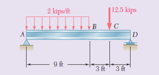
(a) Knowing that σall = 24 ksi and σall = 14.5 ksi, select the most economical wide-flange shape that should be used to support the loading shown. (b) Determine the values to be expected for τm, τm, and the principal stress σmax at the junction of a flange and the web of the selected beam.
Fig. P8.65
(a)
Select the most economical wide flange shape section.
Answer to Problem 65RP
The most economical wide flange shape section is
Explanation of Solution
Given information:
The allowable bending stress
The shear stress
Calculation:
Sketch the free body diagram of beam as shown in figure 1.
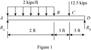
Here,
Calculate the reaction for the given structure:
Taking moment about D,
Summation of vertical force zero.
Calculate the shear force diagram as follows:
Shear force at A is
Shear force at B,
Shear force at C,
Shear force at D,
Maximum shear force occurs at the point where
Consider a section
Calculate the bending moment as follows:
Bending moment at point A,
Bending moment at point B,
Bending moment at point C,
Bending moment at point D,
Sketch the shear force and bending moment diagram as shown in Figure 2.
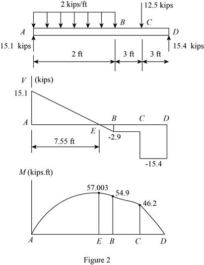
Refer to Figure 2.
The maximum bending moment is
Find the value of
Here,
Substitute
Write the section properties shape as shown in Table 2.
| Shape | |
| 38.4 | |
| 29.0 | |
| 33.4 | |
| 32.4 | |
| 31.2 |
Select the section
The most economical wide flange shape section is
Write the section properties wide flange section as shown in Table 3.
| Shape | W14x22 |
| Area, A | |
| Depth, d | |
| Web thickness, | 0.230 in. |
| Width | 5.000 in. |
| Thickness | 0.335 in. |
Find the area of web
Here, d is the depth of the section and
Substitute
(b)
The value to be expected for
Answer to Problem 65RP
The normal stress
The shear stress
The maximum principal stress is
Explanation of Solution
Calculation:
Point E:
Find the normal stress at point E using the relation:
Here,
Substitute
Thus, the normal stress
Find the value of C using the relation:
Here, d is the depth of section.
Substitute
Find the value of
Here,
Substitute
Find the normal stress
Here,
Substitute
Find the shear stress
The point E is located at top. Since Q is zero.
Thus, the shear stress at point
Point C:
Find the normal stress at point E using the relation:
Here,
Substitute
Find the shear stress point C using the relation:
Here, V is shear force and
Substitute
Thus, the shear stress
Find the
Substitute
Find the R using the relation:
Here,
Substitute
Find the maximum principal stress using the relation:
Substitute
Compare the results,
Select the maximum value of stress for Point B is controls.
Thus, the maximum principal stress is
Want to see more full solutions like this?
Chapter 8 Solutions
Mechanics of Materials, 7th Edition


- (read image, answer given)arrow_forward6/86 The connecting rod AB of a certain internal-combustion engine weighs 1.2 lb with mass center at G and has a radius of gyration about G of 1.12 in. The piston and piston pin A together weigh 1.80 lb. The engine is running at a constant speed of 3000 rev/min, so that the angular velocity of the crank is 3000(2)/60 = 100л rad/sec. Neglect the weights of the components and the force exerted by the gas in the cylinder compared with the dynamic forces generated and calculate the magnitude of the force on the piston pin A for the crank angle 0 = 90°. (Suggestion: Use the alternative moment relation, Eq. 6/3, with B as the moment center.) Answer A = 347 lb 3" 1.3" B 1.7" PROBLEM 6/86arrow_forward6/85 In a study of head injury against the instrument panel of a car during sudden or crash stops where lap belts without shoulder straps or airbags are used, the segmented human model shown in the figure is analyzed. The hip joint O is assumed to remain fixed relative to the car, and the torso above the hip is treated as a rigid body of mass m freely pivoted at O. The center of mass of the torso is at G with the initial position of OG taken as vertical. The radius of gyration of the torso about O is ko. If the car is brought to a sudden stop with a constant deceleration a, determine the speed v relative to the car with which the model's head strikes the instrument panel. Substitute the values m = 50 kg, 7 = 450 mm, r = 800 mm, ko = 550 mm, 0 = 45°, and a = 10g and compute v. Answer v = 11.73 m/s PROBLEM 6/85arrow_forward
- Using AutoCADarrow_forward340 lb 340 lb Δarrow_forward4. In a table of vector differential operators, look up the expressions for V x V in a cylindrical coordinate system. (a) Compute the vorticity for the flow in a round tube where the velocity profile is = vo [1-(³] V₂ = Vo (b) Compute the vorticity for an ideal vortex where the velocity is Ve= r where constant. 2πг (c) Compute the vorticity in the vortex flow given by Ve= r 2лг 1- exp ( r² 4vt (d) Sketch all the velocity and vorticity profiles.arrow_forward
- In the figure, Neglects the heat loss and kinetic and potential energy changes, calculate the work produced by the turbine in kJ T = ??? Steam at P=3 MPa, T = 280°C Turbine Rigid tank V = 1000 m³ Turbine Rigid tank V = 100 m³ V = 1000 m³ V = 100 m³ The valve is opened. Initially: evacuated (empty) tank O a. 802.8 Initially: Closed valve O b. 572 O c. 159.93 Od. 415 e. 627.76 equilibriumarrow_forwardPlease find the torsional yield strength, the yield strength, the spring index, and the mean diameter. Use: E = 28.6 Mpsi, G = 11.5 Mpsi, A = 140 kpsi·in, m = 0.190, and relative cost= 1.arrow_forwardA viscoelastic column is made of a material with a creep compliance of D(t)= 0.75+0.5log10t+0.18(log10t)^2 GPA^-1 for t in s. If a constant compressive stress of σ0 = –100 MPa is applied at t = 0, how long will it take (= t1/2) for the height of the column to decrease to ½ its original value? Note: You will obtain multiple answers for this problem! One makes sense physically and one does not.arrow_forward
- A group of 23 power transistors, dissipating 2 W each, are to be cooled by attaching them to a black-anodized square aluminum plate and mounting the plate on the wall of a room at 30°C. The emissivity of the transistor and the plate surfaces is 0.9. Assuming the heat transfer from the back side of the plate to be negligible and the temperature of the surrounding surfaces to be the same as the air temperature of the room, determine the length of the square plate if the average surface temperature of the plate is not to exceed 50°C. Start the iteration process with an initial guess of the size of the plate as 43 cm. The properties of air at 1 atm and the film temperature of (Ts + T)/2 = (50 + 30)/2 = 40°C are k = 0.02662 W/m·°C, ν = 1.702 × 10⁻⁵ m2 /s, Pr = 0.7255, and β = 0.003195 K–1. Multiple Choice 0.473 m 0.284 m 0.513 m 0.671 marrow_forwardA 40-cm-diameter, 127-cm-high cylindrical hot water tank is located in the bathroom of a house maintained at 20°C. The surface temperature of the tank is measured to be 44°C and its emissivity is 0.4. Taking the surrounding surface temperature to be also 20°C, determine the rate of heat loss from all surfaces of the tank by natural convection and radiation. The properties of air at 32°C are k=0.02603 W/m-K, v=1.627 x 10⁻⁵ m²/s, Pr = 0.7276, and ẞ = 0.003279 K-1 The rate of heat loss from all surfaces of the tank by natural convection is The rate of heat loss from all surfaces of the tank by radiation is W. W.arrow_forwardA 2.5-m-long thin vertical plate is subjected to uniform heat flux on one side, while the other side is exposed to cool air at 5°C. The plate surface has an emissivity of 0.73, and its midpoint temperature is 55°C. Determine the heat flux subjected on the plate surface. Uniform heat flux -Plate, € = 0.73 Cool air 5°C 7 TSUIT Given: The properties of water at Tf,c= 30°C. k=0.02588 W/m.K, v=1.608 x 10⁻⁵ m²/s Pr = 0.7282 The heat flux subjected on the plate surface is W/m²arrow_forward
 Elements Of ElectromagneticsMechanical EngineeringISBN:9780190698614Author:Sadiku, Matthew N. O.Publisher:Oxford University Press
 Mechanics of Materials (10th Edition)Mechanical EngineeringISBN:9780134319650Author:Russell C. HibbelerPublisher:PEARSON
 Thermodynamics: An Engineering ApproachMechanical EngineeringISBN:9781259822674Author:Yunus A. Cengel Dr., Michael A. BolesPublisher:McGraw-Hill Education
 Control Systems EngineeringMechanical EngineeringISBN:9781118170519Author:Norman S. NisePublisher:WILEY
 Mechanics of Materials (MindTap Course List)Mechanical EngineeringISBN:9781337093347Author:Barry J. Goodno, James M. GerePublisher:Cengage Learning
 Engineering Mechanics: StaticsMechanical EngineeringISBN:9781118807330Author:James L. Meriam, L. G. Kraige, J. N. BoltonPublisher:WILEY