
Concept explainers
Videos
The compressed-air tank AB has a 250-rnm outside diameter and an 8-mm wall thickness. It is fitted with a collar by which a 40-kN force P is applied at B in the horizontal direction. Knowing that the gage pressure inside the tank is 5 MPa, determine the maximum normal stress and the maximum shearing stress at point K.
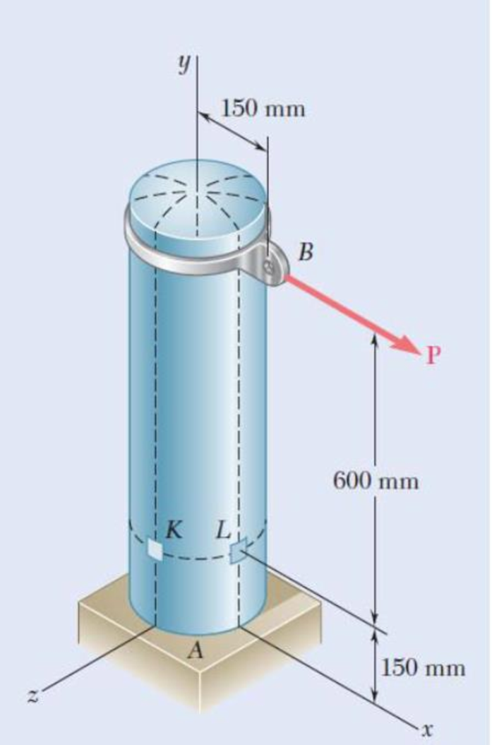
Fig. P7.124
Find the maximum normal stress and maximum shear stress at point K.
Answer to Problem 124P
The maximum normal stress and maximum shear stress at point K are
Explanation of Solution
Given information:
The outer diameter (d) of the tank is
The wall thickness (t) of the tank is
The magnitude of the load P is
The gage pressure (p) inside the tank is
Calculation:
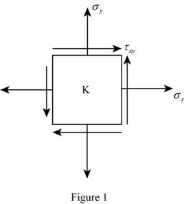
Consider an element at point K.
Show the stress acting on the point K as shown in Figure 1.
Calculate the inner radius of the vessel
Substitute
Show the expression for hoop stress acting on the tank as shown below.
Substitute
Show the expression for longitudinal stress acting on the vessel as shown below.
Substitute
Calculate the stress due to bending at point K as follows:
The point K lies in the neutral axis, then
The stress due to bending at point K,
Calculate the stress due to transverse shear as follows:
Consider the shear force acting on the tank is denoted by V. Then,
Consider the distance between the centre of the circular cross-section to the inner and outer surface of the wall are denoted by
Calculate the shear flow Q using the relation:
Substitute
Calculate the moment of inertia I of the cross-section using the relation:
Substitute
Calculate the shear stress using the relation:
Substitute
Show the total hoop stress
Calculate the radius of the Mohr circle using the relation:
Substitute
Show the expression for average stress acting on the vessel as shown below.
Substitute
Consider the principal stress are denoted by
Calculate the value of the
Substitute
Calculate the value of the
Substitute
The stress at point C is 0. Then,
Compare the value of stress
Get the maximum and minimum value of the stress as follows:
Thus, the maximum normal stress in the tank is
Calculate the maximum shear stress in the tank using the relation:
Substitute
Thus, the maximum shear stress in the tank is
Want to see more full solutions like this?
Chapter 7 Solutions
EBK MECHANICS OF MATERIALS


- Solve this probem and show all of the workarrow_forwardThe differential equation of a cruise control system is provided by the following equation: WRITE OUT SOLUTION DO NOT USE A COPIED SOLUTION Find the closed loop transfer function with respect to the reference velocity (vr) . a. Find the poles of the closed loop transfer function for different values of K. How does the poles move as you change K? b. Find the step response for different values of K and plot in MATLAB. What can you observe?arrow_forwardSolve this problem and show all of the workarrow_forward
- Determine the minimum applied force P required to move wedge A to the right. The spring is compressed a distance of 175 mm. Neglect the weight of A and B. The coefficient of static friction for all contacting surface is μs = 0.35. Neglect friction at the rollers. k = = 15 kN/m P A B 10°arrow_forwardDO NOT COPY SOLUTION- will report The differential equation of a cruise control system is provided by the following equation: Find the closed loop transfer function with respect to the reference velocity (vr) . a. Find the poles of the closed loop transfer function for different values of K. How does the poles move as you change K? b. Find the step response for different values of K and plot in MATLAB. What can you observe?arrow_forwarda box shaped barge 37m long, 6.4 m beam, floats at an even keel draught of 2.5 m in water density 1.025 kg/m3. If a mass is added and the vessel moves into water density 1000 kg/m3, determine the magnitude of this mass if the fore end and aft end draughts are 2.4m and 3.8m respectively.arrow_forward
- a ship 125m long and 17.5m beam floats in seawater of 1.025 t/m3 at a draught of 8m. the waterplane coefficient is 0.83, block coefficient 0.759 and midship section area coefficient 0.98. calculate i) prismatic coefficient ii) TPC iii) change in mean draught if the vessel moves into water of 1.016 t/m3arrow_forwardc. For the given transfer function, find tp, ts, tr, Mp . Plot the resulting step response. G(s) = 40/(s^2 + 4s + 40) handplot only, and solve for eacharrow_forwardA ship of 9000 tonne displacement floats in fresh water of 1.000 t/m3 at a draught 50 mm below the sea water line. The waterplane area is 1650 m2. Calculate the mass of cargo which must be added so that when entering seawater of 1.025 t/m3 it floats at the seawater line.arrow_forward
- A ship of 15000 tonne displacement floats at a draught of 7 metres in water of 1.000t/cub. Metre.It is required to load the maximum amount of oil to give the ship a draught of 7.0 metre in seawater ofdensity 1.025 t/cub.metre. If the waterplane area is 2150 square metre, calculate the massof oil requiredarrow_forwardA ship of 8000 tonne displacement floats in seawater of 1.025 t/m3 and has a TPC of 14. The vessel moves into fresh water of 1.000 t/m3 and loads 300 tonne of oil fuel. Calculate the change in mean draught.arrow_forwardAuto Controls DONT COPY ANSWERS - will report Perform the partial fraction expansion of the following transfer function and find the impulse response: G(s) = (s/2 + 5/3) / (s^2 + 4s + 6) G(s) =( 6s^2 + 50) / (s+3)(s^2 +4)arrow_forward
 Elements Of ElectromagneticsMechanical EngineeringISBN:9780190698614Author:Sadiku, Matthew N. O.Publisher:Oxford University Press
 Mechanics of Materials (10th Edition)Mechanical EngineeringISBN:9780134319650Author:Russell C. HibbelerPublisher:PEARSON
 Thermodynamics: An Engineering ApproachMechanical EngineeringISBN:9781259822674Author:Yunus A. Cengel Dr., Michael A. BolesPublisher:McGraw-Hill Education
 Control Systems EngineeringMechanical EngineeringISBN:9781118170519Author:Norman S. NisePublisher:WILEY
 Mechanics of Materials (MindTap Course List)Mechanical EngineeringISBN:9781337093347Author:Barry J. Goodno, James M. GerePublisher:Cengage Learning
 Engineering Mechanics: StaticsMechanical EngineeringISBN:9781118807330Author:James L. Meriam, L. G. Kraige, J. N. BoltonPublisher:WILEY