
EBK MECHANICS OF MATERIALS
7th Edition
ISBN: 8220100257063
Author: BEER
Publisher: YUZU
expand_more
expand_more
format_list_bulleted
Videos
Textbook Question
Chapter 7.9, Problem 129P
7.128 through 7.131 For the given state of plane strain, use the method of Sec. 7.7A to determine the state of plane strain associated with axes x' and y' rotated through the given angle
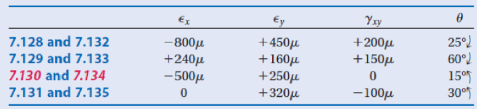
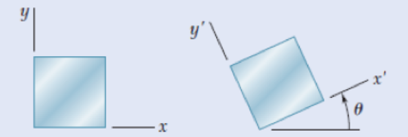
Fig. P7.128 through P7.135
Expert Solution & Answer
Want to see the full answer?
Check out a sample textbook solution
Students have asked these similar questions
Please solve this problem as soon as possible My ID# 016948724
The gears shown in the figure have a diametral pitch of 2 teeth per inch and a 20° pressure angle.
The pinion rotates at 1800 rev/min clockwise and transmits 200 hp through the idler pair to gear
5 on shaft c. What forces do gears 3 and 4 transmit to the idler shaft?
TS
I
y
18T
32T
This
a
12
x
18T
C
48T
5
Question 1. Draw 3 teeth for the following pinion and gear respectively. The teeth
should be drawn near the pressure line so that the teeth from the pinion should
mesh those of the gear. Drawing scale (1:1). Either a precise hand drawing or
CAD drawing is acceptable. Draw all the trajectories of the involute lines and the
circles.
Specification: 18tooth pinion and 30tooth gear. Diameter pitch=P=6 teeth /inch.
Pressure angle:20°, 1/P for addendum (a) and 1.25/P for dedendum (b). For fillet,
c=b-a.
Chapter 7 Solutions
EBK MECHANICS OF MATERIALS
Ch. 7.1 - 7.1 through 7.4 For the given state of stress,...Ch. 7.1 - 7.1 through 7.4 For the given state of stress,...Ch. 7.1 - 7.1 through 7.4 For the given state of stress,...Ch. 7.1 - 7.1 through 7.4 For the given state of stress,...Ch. 7.1 - 7.5 through 7.8 For the given state of stress,...Ch. 7.1 - 7.5 through 7.8 For the given state of stress,...Ch. 7.1 - 7.5 through 7.8 For the given state of stress,...Ch. 7.1 - 7.5 through 7.8 For the given state of stress,...Ch. 7.1 - 7.9 through 7.12 For the given state of stress,...Ch. 7.1 - 7.9 through 7.12 For the given state of stress,...
Ch. 7.1 - 7.9 through 7.12 For the given state of stress,...Ch. 7.1 - 7.9 through 7.12 For the given state of stress,...Ch. 7.1 - 7.13 through 7.16 For the given state of stress,...Ch. 7.1 - 7.13 through 7.16 For the given state of stress,...Ch. 7.1 - 7.13 through 7.16 For the given state of stress,...Ch. 7.1 - 7.13 through 7.16 For the given state of stress,...Ch. 7.1 - 7.17 and 7.18 The grain of a wooden member forms...Ch. 7.1 - 7.17 and 7.18 The grain of a wooden member forms...Ch. 7.1 - Two wooden members of 80 120-mm uniform...Ch. 7.1 - Two wooden members of 80 120-mm uniform...Ch. 7.1 - The centric force P is applied to a short post as...Ch. 7.1 - Two members of uniform cross section 50 80 mm are...Ch. 7.1 - The axle of an automobile is acted upon by the...Ch. 7.1 - A 400-lb vertical force is applied at D to a gear...Ch. 7.1 - A mechanic uses a crowfoot wrench to loosen a bolt...Ch. 7.1 - The steel pipe AB has a 102-mm outer diameter and...Ch. 7.1 - For the state of plane stress shown, determine the...Ch. 7.1 - For the state of plane stress shown, determine (a)...Ch. 7.1 - For the state of plane stress shown, determine (a)...Ch. 7.1 - Determine the range of values of x for which the...Ch. 7.2 - Solve Probs. 7.5 and 7.9, using Mohr's circle. 7.5...Ch. 7.2 - Solve Probs. 7.7 and 7.11, using Mohrs circle. 7.5...Ch. 7.2 - Solve Prob. 7.10, using Mohrs circle. 7.9 through...Ch. 7.2 - Solve Prob. 7.12, using Mohr's circle. 7.9 through...Ch. 7.2 - Solve Prob. 7.13, using Mohr's circle. 7.13...Ch. 7.2 - Solve Prob. 7.14, using Mohr's circle. 7.13...Ch. 7.2 - Solve Prob. 7.15, using Mohr's circle. 7.13...Ch. 7.2 - Solve Prob. 7.16, using Mohr's circle. 7.13...Ch. 7.2 - Solve Prob. 7.17, using Mohr's circle. 7.17 and...Ch. 7.2 - Solve Prob. 7.18, using Mohr's circle. 7.17 and...Ch. 7.2 - Solve Prob. 7.19, using Mohr's circle. 7.19 Two...Ch. 7.2 - Solve Prob. 7.20, using Mohr's circle. 7.20 Two...Ch. 7.2 - Solve Prob. 7.21, using Mohrs circle. 7.21 The...Ch. 7.2 - Solve Prob. 7.22, using Mohrs circle. 7.22 Two...Ch. 7.2 - Solve Prob. 7.23, using Mohr's circle. 7.23 The...Ch. 7.2 - Solve Prob. 7.24, using Mohr's circle 7.24 A...Ch. 7.2 - Solve Prob. 7.25, using Mohrs circle. 7.25 A...Ch. 7.2 - Solve Prob. 7.26, using Mohrs circle. 7.26 The...Ch. 7.2 - Solve Prob. 7.27, using Mohr's circle. 7.27 For...Ch. 7.2 - Solve Prob. 7.28, using Mohrs circle. 7.28 For the...Ch. 7.2 - Solve Prob. 7.29, using Mohr's circle. 7.29 For...Ch. 7.2 - Solve Prob. 7.30, using Mohrs circle. 7.30...Ch. 7.2 - Solve Prob. 7.29, using Mohr's circle and assuming...Ch. 7.2 - 7.54 and 7.55 Determine the principal planes and...Ch. 7.2 - 7.54 and 7.55 Determine the principal planes and...Ch. 7.2 - 7.56 and 7.57 Determine the principal planes and...Ch. 7.2 - 7.56 and 7.57 Determine the principal planes and...Ch. 7.2 - For the element shown, determine the range of...Ch. 7.2 - For the element shown, determine the range of...Ch. 7.2 - For the state of stress shown, determine the range...Ch. 7.2 - For the state of stress shown, determine the range...Ch. 7.2 - For the state of stress shown, determine the range...Ch. 7.2 - For the state of stress shown, it is known that...Ch. 7.2 - The Mohr's circle shown corresponds to the state...Ch. 7.2 - (a) Prove that the expression xy 2xywhere x,...Ch. 7.5 - For the state of plane stress shown, determine the...Ch. 7.5 - For the state of plane stress shown, determine the...Ch. 7.5 - For the state of stress shown, determine the...Ch. 7.5 - For the state of stress shown, determine the...Ch. 7.5 - 7.70 and 7.71 For the state of stress shown,...Ch. 7.5 - 7.70 and 7.71 For the state of stress shown,...Ch. 7.5 - 7.72 and 7.73 For the state of stress shown,...Ch. 7.5 - 7.72 and 7.73 For the state of stress shown,...Ch. 7.5 - For the state of stress shown, determine the value...Ch. 7.5 - For the state of stress shown, determine the value...Ch. 7.5 - Prob. 76PCh. 7.5 - For the state of stress shown, determine two...Ch. 7.5 - For the state of stress shown, determine the range...Ch. 7.5 - Prob. 79PCh. 7.5 - Prob. 80PCh. 7.5 - The state of plane stress shown occurs in a...Ch. 7.5 - Prob. 82PCh. 7.5 - The state of plane stress shown occurs in a...Ch. 7.5 - Solve Prob. 7.83, using the...Ch. 7.5 - The 38-mm-diameter shaft AB is made of a grade of...Ch. 7.5 - Solve Prob. 7.85, using the...Ch. 7.5 - The 1.5-in.-diameter shaft AB is made of a grade...Ch. 7.5 - Prob. 88PCh. 7.5 - Prob. 89PCh. 7.5 - Prob. 90PCh. 7.5 - Prob. 91PCh. 7.5 - Prob. 92PCh. 7.5 - Prob. 93PCh. 7.5 - Prob. 94PCh. 7.5 - Prob. 95PCh. 7.5 - Prob. 96PCh. 7.5 - Prob. 97PCh. 7.6 - A spherical pressure vessel has an outer diameter...Ch. 7.6 - A spherical gas container having an inner diameter...Ch. 7.6 - The maximum gage pressure is known to be 1150 psi...Ch. 7.6 - Prob. 101PCh. 7.6 - Prob. 102PCh. 7.6 - A basketball has a 300-mm outer diameter and a...Ch. 7.6 - The unpressurized cylindrical storage tank shown...Ch. 7.6 - Prob. 105PCh. 7.6 - Prob. 106PCh. 7.6 - Prob. 107PCh. 7.6 - Prob. 108PCh. 7.6 - Prob. 109PCh. 7.6 - Prob. 110PCh. 7.6 - Prob. 111PCh. 7.6 - The cylindrical portion of the compressed-air tank...Ch. 7.6 - Prob. 113PCh. 7.6 - Prob. 114PCh. 7.6 - Prob. 115PCh. 7.6 - Square plates, each of 0.5-in. thickness, can be...Ch. 7.6 - The pressure tank shown has a 0.375-in. wall...Ch. 7.6 - Prob. 118PCh. 7.6 - Prob. 119PCh. 7.6 - A pressure vessel of 10-in. inner diameter and...Ch. 7.6 - Prob. 121PCh. 7.6 - A torque of magnitude T = 12 kN-m is applied to...Ch. 7.6 - The tank shown has a 180-mm inner diameter and a...Ch. 7.6 - The compressed-air tank AB has a 250-rnm outside...Ch. 7.6 - In Prob. 7.124, determine the maximum normal...Ch. 7.6 - Prob. 126PCh. 7.6 - Prob. 127PCh. 7.9 - 7.128 through 7.131 For the given state of plane...Ch. 7.9 - 7.128 through 7.131 For the given state of plane...Ch. 7.9 - Prob. 130PCh. 7.9 - 7.128 through 7.131 For the given state of plane...Ch. 7.9 - Prob. 132PCh. 7.9 - Prob. 133PCh. 7.9 - Prob. 134PCh. 7.9 - 7.128 through 7.131 For the given state of plane...Ch. 7.9 - 7.136 through 7.139 The following state of strain...Ch. 7.9 - Prob. 137PCh. 7.9 - Prob. 138PCh. 7.9 - Prob. 139PCh. 7.9 - Prob. 140PCh. 7.9 - 7.140 through 7.143 For the given state of plane...Ch. 7.9 - Prob. 142PCh. 7.9 - Prob. 143PCh. 7.9 - Prob. 144PCh. 7.9 - The strains determined by the use of the rosette...Ch. 7.9 - Prob. 146PCh. 7.9 - Prob. 147PCh. 7.9 - Show that the sum of the three strain measurements...Ch. 7.9 - Prob. 149PCh. 7.9 - Prob. 150PCh. 7.9 - Solve Prob. 7.150, assuming that the rosette at...Ch. 7.9 - Prob. 152PCh. 7.9 - Prob. 153PCh. 7.9 - Prob. 154PCh. 7.9 - Prob. 155PCh. 7.9 - The given state of plane stress is known to exist...Ch. 7.9 - The following state of strain has been determined...Ch. 7 - A steel pipe of 12-in. outer diameter is...Ch. 7 - Two steel plates of uniform cross section 10 80...Ch. 7 - Prob. 160RPCh. 7 - Prob. 161RPCh. 7 - For the state of stress shown, determine the...Ch. 7 - For the state of stress shown, determine the value...Ch. 7 - The state of plane stress shown occurs in a...Ch. 7 - The compressed-air tank AB has an inner diameter...Ch. 7 - For the compressed-air tank and loading of Prob....Ch. 7 - Prob. 167RPCh. 7 - Prob. 168RPCh. 7 - Prob. 169RP
Knowledge Booster


Learn more about
Need a deep-dive on the concept behind this application? Look no further. Learn more about this topic, mechanical-engineering and related others by exploring similar questions and additional content below.Similar questions
- 5. The figure shows a gear train. There is no friction at the bearings except for the gear tooth forces. The material of the milled gears is steel having a Brinell hardness of 170. The input shaft speed (n2) is 800 rpm. The face width and the contact angle for all gears are 1 in and 20° respectively. In this gear set, the endurance limit (Se) is 15 kpsi and nd (design factor) is 2. (a) Find the revolution speed of gear 5. (b) Determine whether each gear satisfies the design factor of 2.0 for bending fatigue. (c) Determine whether each gear satisfies the design factor of 2.0 for surface fatigue (contact stress). (d) According to the computation results of the questions (b) and (c), explain the possible failure mechanisms for each gear. N4=28 800rpm N₁=43 N5=34 N₂=14 P(diameteral pitch)=8 for all gears Coupled to 2.5hp motorarrow_forward1. The rotating steel shaft is simply supported by bearings at points of B and C, and is driven by a spur gear at D, which has a 6-in pitch diameter. The force F from the drive gear acts at a pressure angle of 20°. The shaft transmits a torque to point A of TA =3000 lbĘ in. The shaft is machined from steel with Sy=60kpsi and Sut=80 kpsi. (1) Draw a shear force diagram and a bending moment diagram by F. According to your analysis, where is the point of interest to evaluate the safety factor among A, B, C, and D? Describe the reason. (Hint: To find F, the torque Tд is generated by the tangential force of F (i.e. Ftangential-Fcos20°) When n=2.5, K=1.8, and K₁ =1.3, determine the diameter of the shaft based on (2) static analysis using DE theory (note that fatigue stress concentration factors need to be used for this question because the loading condition is fatigue) and (3) a fatigue analysis using modified Goodman. Note) A standard diameter is not required for the questions. 10 in Darrow_forward3 N2=28 P(diametral pitch)=8 for all gears Coupled to 25 hp motor N3=34 Full depth spur gears with pressure angle=20° N₂=2000 rpm (1) Compute the circular pitch, the center-to-center distance, and base circle radii. (2) Draw the free body diagram of gear 3 and show all the forces and the torque. (3) In mounting gears, the center-to-center distance was reduced by 0.1 inch. Calculate the new values of center-to-center distance, pressure angle, base circle radii, and pitch circle diameters. (4)What is the new tangential and radial forces for gear 3? (5) Under the new center to center distance, is the contact ratio (mc) increasing or decreasing?arrow_forward
- 2. A flat belt drive consists of two 4-ft diameter cast-iron pulleys spaced 16 ft apart. A power of 60 hp is transmitted by a pulley whose speed is 380 rev/min. Use a service factor (Ks) pf 1.1 and a design factor 1.0. The width of the polyamide A-3 belt is 6 in. Use CD=1. Answer the following questions. (1) What is the total length of the belt according to the given geometry? (2) Find the centrifugal force (Fc) applied to the belt. (3) What is the transmitted torque through the pulley system given 60hp? (4) Using the allowable tension, find the force (F₁) on the tight side. What is the tension at the loose side (F2) and the initial tension (F.)? (5) Using the forces, estimate the developed friction coefficient (f) (6) Based on the forces and the given rotational speed, rate the pulley set. In other words, what is the horse power that can be transmitted by the pulley system? (7) To reduce the applied tension on the tight side, the friction coefficient is increased to 0.75. Find out the…arrow_forwardThe tooth numbers for the gear train illustrated are N₂ = 24, N3 = 18, №4 = 30, №6 = 36, and N₁ = 54. Gear 7 is fixed. If shaft b is turned through 5 revolutions, how many turns will shaft a make? a 5 [6] barrow_forwardCE-112 please solve this problem step by step and give me the correct answerarrow_forward
- CE-112 please solve this problem step by step and give me the correct answerarrow_forwardCE-112 solve this problem step by step and give me the correct answer pleasearrow_forwardPlease do not use any AI tools to solve this question. I need a fully manual, step-by-step solution with clear explanations, as if it were done by a human tutor. No AI-generated responses, please.arrow_forward
- Please do not use any AI tools to solve this question. I need a fully manual, step-by-step solution with clear explanations, as if it were done by a human tutor. No AI-generated responses, please.arrow_forwardCE-112 please solve this problem step by step and give me the correct answerarrow_forwardCE-112 please solve this problem step by step and give me the correct asnwerarrow_forward
arrow_back_ios
SEE MORE QUESTIONS
arrow_forward_ios
Recommended textbooks for you
 Elements Of ElectromagneticsMechanical EngineeringISBN:9780190698614Author:Sadiku, Matthew N. O.Publisher:Oxford University Press
 Mechanics of Materials (10th Edition)Mechanical EngineeringISBN:9780134319650Author:Russell C. HibbelerPublisher:PEARSON
 Thermodynamics: An Engineering ApproachMechanical EngineeringISBN:9781259822674Author:Yunus A. Cengel Dr., Michael A. BolesPublisher:McGraw-Hill Education
 Control Systems EngineeringMechanical EngineeringISBN:9781118170519Author:Norman S. NisePublisher:WILEY
 Mechanics of Materials (MindTap Course List)Mechanical EngineeringISBN:9781337093347Author:Barry J. Goodno, James M. GerePublisher:Cengage Learning
 Engineering Mechanics: StaticsMechanical EngineeringISBN:9781118807330Author:James L. Meriam, L. G. Kraige, J. N. BoltonPublisher:WILEY
Elements Of Electromagnetics
Mechanical Engineering
ISBN:9780190698614
Author:Sadiku, Matthew N. O.
Publisher:Oxford University Press
Mechanics of Materials (10th Edition)
Mechanical Engineering
ISBN:9780134319650
Author:Russell C. Hibbeler
Publisher:PEARSON
Thermodynamics: An Engineering Approach
Mechanical Engineering
ISBN:9781259822674
Author:Yunus A. Cengel Dr., Michael A. Boles
Publisher:McGraw-Hill Education
Control Systems Engineering
Mechanical Engineering
ISBN:9781118170519
Author:Norman S. Nise
Publisher:WILEY
Mechanics of Materials (MindTap Course List)
Mechanical Engineering
ISBN:9781337093347
Author:Barry J. Goodno, James M. Gere
Publisher:Cengage Learning
Engineering Mechanics: Statics
Mechanical Engineering
ISBN:9781118807330
Author:James L. Meriam, L. G. Kraige, J. N. Bolton
Publisher:WILEY
An Introduction to Stress and Strain; Author: The Efficient Engineer;https://www.youtube.com/watch?v=aQf6Q8t1FQE;License: Standard YouTube License, CC-BY