
Videos
In each case, identify any two-force members, and then draw the free body diagrams of each member of the frame.
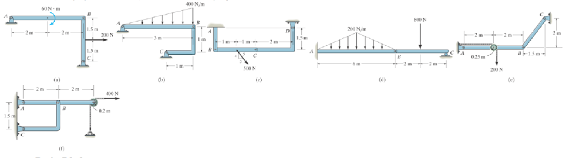
Prob. P6-3
(a)
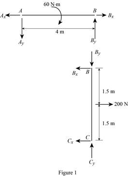
To identify and draw: The two force members and the free body diagrams of each member of the frame.
Explanation of Solution
Assumptions:
- Consider the state of member as tension where the force is pulling the member and as compression where the force is pushing the member.
- Consider the force indicating right side as positive and left side as negative in horizontal components of forces.
- Consider the force indicating upside is taken as positive and downside as negative in vertical components of forces.
Show the free body diagram of the member of the frame as in Figure (1).
(b)
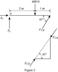
To identify and draw: The two force members and the free body diagrams of each member of the frame.
Explanation of Solution
Assumptions:
- Consider the state of member as tension where the force is pulling the member and as compression where the force is pushing the member.
- Consider the force indicating right side as positive and left side as negative in horizontal components of forces.
- Consider the force indicating upside is taken as positive and downside as negative in vertical components of forces.
The member CB is a two force member.
Show the free body diagram of the members of the frame as in Figure (2).
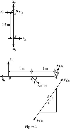
(c)
To identify and draw: The two force members and the free body diagrams of each member of the frame.
Explanation of Solution
Assumptions:
- Consider the state of member as tension where the force is pulling the member and as compression where the force is pushing the member.
- Consider the force indicating right side as positive and left side as negative in horizontal components of forces.
- Consider the force indicating upside is taken as positive and downside as negative in vertical components of forces.
The member CD is a two force member.
Show the free body diagram of the members of the frame as in Figure (3).
(d)
To identify and draw: The two force members and the free body diagrams of each member of the frame.
Explanation of Solution
Assumptions:
- Consider the state of member as tension where the force is pulling the member and as compression where the force is pushing the member.
- Consider the force indicating right side as positive and left side as negative in horizontal components of forces.
- Consider the force indicating upside is taken as positive and downside as negative in vertical components of forces.
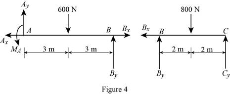
Show the free body diagram of the members of the frame as in Figure (4).
(e)
To identify and draw: The two force members and the free body diagrams of each member of the frame.
Explanation of Solution
Assumptions:
- Consider the state of member as tension where the force is pulling the member and as compression where the force is pushing the member.
- Consider the force indicating right side as positive and left side as negative in horizontal components of forces.
- Consider the force indicating upside is taken as positive and downside as negative in vertical components of forces.
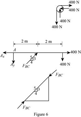
The member BC is a two force member.
Show the free body diagram of the members of the frame as in Figure (5).

(f)
To identify and draw: The two force members and the free body diagrams of each member of the frame.
Explanation of Solution
Assumptions:
- Consider the state of member as tension where the force is pulling the member and as compression where the force is pushing the member.
- Consider the force indicating right side as positive and left side as negative in horizontal components of forces.
- Consider the force indicating upside is taken as positive and downside as negative in vertical components of forces.
The member BC is a two force member.
Show the free body diagram of the members of the frame as in Figure (5).
Want to see more full solutions like this?
Chapter 6 Solutions
INTERNATIONAL EDITION---Engineering Mechanics: Statics, 14th edition (SI unit)
Additional Engineering Textbook Solutions
Starting Out with Programming Logic and Design (5th Edition) (What's New in Computer Science)
Starting Out with Python (4th Edition)
Starting Out with Java: From Control Structures through Objects (7th Edition) (What's New in Computer Science)
Mechanics of Materials (10th Edition)
Degarmo's Materials And Processes In Manufacturing
Java: An Introduction to Problem Solving and Programming (8th Edition)


- Experiment تكنولوجيا السيارات - Internal Forced convenction Heat transfer Air Flow through Rectangular Duct. objective: Study the convection heat transfer of air flow through rectangular duct. Valve Th Top Dead Centre Exhaust Valve Class CP. N; ~ RIVavg Ti K 2.11 Te To 18.8 21.3 45.8 Nath Ne Pre Calculations:. Q = m cp (Te-Ti) m: Varg Ac Acca*b Q=hexp As (Ts-Tm) 2 2.61 18.5 20.846.3 Tm = Te-Ti = 25 AS-PL = (a+b)*2*L Nu exp= Re-Vavy D heep Dh k 2ab a+b Nu Dh the- (TS-Tm) Ts. Tmy Name / Nu exp Naxe بب ارتدان العشريarrow_forwardProcedure:1- Cartesian system, 2D3D,type of support2- Free body diagram3 - Find the support reactions4- If you find a negativenumber then flip the force5- Find the internal force3D∑Fx=0∑Fy=0∑Fz=0∑Mx=0∑My=0\Sigma Mz=02D\Sigma Fx=0\Sigma Fy=0\Sigma Mz=05- Use method of sectionand cut the elementwhere you want to findarrow_forwardProcedure:1- Cartesian system, 2D3D,type of support2- Free body diagram3 - Find the support reactions4- If you find a negativenumber then flip the force5- Find the internal force3D∑Fx=0∑Fy=0∑Fz=0∑Mx=0∑My=0\Sigma Mz=02D\Sigma Fx=0\Sigma Fy=0\Sigma Mz=05- Use method of sectionand cut the elementwhere you want to findthe internal force andkeep either side of thearrow_forward
- Procedure: 1- Cartesian system, 2D3D, type of support 2- Free body diagram 3 - Find the support reactions 4- If you find a negative number then flip the force 5- Find the internal force 3D ∑Fx=0 ∑Fy=0 ∑Fz=0 ∑Mx=0 ∑My=0 ΣMz=0 2D ΣFx=0 ΣFy=0 ΣMz=0 5- Use method of section and cut the element where you want to find the internal force and keep either side of thearrow_forwardProcedure:1- Cartesian system, 2D3D,type of support2- Free body diagram3 - Find the support reactions4- If you find a negativenumber then flip the force5- Find the internal force3D∑Fx=0∑Fy=0∑Fz=0∑Mx=0∑My=0\Sigma Mz=02D\Sigma Fx=0\Sigma Fy=0\Sigma Mz=05- Use method of sectionand cut the elementwhere you want to findthe internal force andkeep either side of thearrow_forwardProcedure: 1- Cartesian system, 2(D)/(3)D, type of support 2- Free body diagram 3 - Find the support reactions 4- If you find a negative number then flip the force 5- Find the internal force 3D \sum Fx=0 \sum Fy=0 \sum Fz=0 \sum Mx=0 \sum My=0 \Sigma Mz=0 2D \Sigma Fx=0 \Sigma Fy=0 \Sigma Mz=0 5- Use method of section and cut the element where you want to find the internal force and keep either side of the sectionarrow_forward
- Procedure: 1- Cartesian system, 2(D)/(3)D, type of support 2- Free body diagram 3 - Find the support reactions 4- If you find a negative number then flip the force 5- Find the internal force 3D \sum Fx=0 \sum Fy=0 \sum Fz=0 \sum Mx=0 \sum My=0 \Sigma Mz=0 2D \Sigma Fx=0 \Sigma Fy=0 \Sigma Mz=0 5- Use method of section and cut the element where you want to find the internal force and keep either side of the sectionarrow_forwardFor each system below with transfer function G(s), plot the pole(s) on the s-plane. and indicate whether the system is: (a) "stable" (i.e., a bounded input will always result in a bounded output), (b) "marginally stable," or (c) "unstable" Sketch a rough graph of the time response to a step input. 8 a) G(s) = 5-5 8 b) G(s) = c) G(s) = = s+5 3s + 8 s² - 2s +2 3s +8 d) G(s): = s²+2s+2 3s+8 e) G(s): = s² +9 f) G(s): 8 00 == Sarrow_forwardPlease answer the following question. Include all work and plase explain. Graphs are provided below. "Consider the Mg (Magnesium) - Ni (Nickel) phase diagram shown below. This phase diagram contains two eutectic reactions and two intermediate phases (Mg2Ni and MgNi2). At a temperature of 505oC, determine what the composition of an alloy would need to be to contain a mass fraction of 0.20 Mg and 0.80 Mg2Ni."arrow_forward
- The triangular plate, having a 90∘∘ angle at AA, supports the load PP = 370 lblb as shown in (Figure 1).arrow_forwardDesign a 4-bar linkage to carry the body in Figure 1 through the two positions P1 and P2 at the angles shown in the figure. Use analytical synthesis with the free choice values z = 1.075, q= 210°, ß2 = −27° for left side and s = 1.24, y= 74°, ½ = − 40° for right side. φ 1.236 P2 147.5° 210° 2.138 P1 Figure 1 Xarrow_forwardDesign a 4-bar linkage to carry the body in Figure 1 through the two positions P1 and P2 at the angles shown in the figure. Use analytical synthesis with the free choice values z = 1.075, q= 210°, B₂ = −27° for left side and s = 1.24, y= 74°, ½ = − 40° for right side. 1.236 P2 147.5° 210° P1 Figure 1 2.138 Xarrow_forward
 Elements Of ElectromagneticsMechanical EngineeringISBN:9780190698614Author:Sadiku, Matthew N. O.Publisher:Oxford University Press
 Mechanics of Materials (10th Edition)Mechanical EngineeringISBN:9780134319650Author:Russell C. HibbelerPublisher:PEARSON
 Thermodynamics: An Engineering ApproachMechanical EngineeringISBN:9781259822674Author:Yunus A. Cengel Dr., Michael A. BolesPublisher:McGraw-Hill Education
 Control Systems EngineeringMechanical EngineeringISBN:9781118170519Author:Norman S. NisePublisher:WILEY
 Mechanics of Materials (MindTap Course List)Mechanical EngineeringISBN:9781337093347Author:Barry J. Goodno, James M. GerePublisher:Cengage Learning
 Engineering Mechanics: StaticsMechanical EngineeringISBN:9781118807330Author:James L. Meriam, L. G. Kraige, J. N. BoltonPublisher:WILEY