
INTERNATIONAL EDITION---Engineering Mechanics: Statics, 14th edition (SI unit)
14th Edition
ISBN: 9780133918922
Author: Russell C. Hibbeler
Publisher: PEARSON
expand_more
expand_more
format_list_bulleted
Videos
Textbook Question
Chapter 6.6, Problem 81P
Determine the force the load creates in member DB and in member FB, which contains the hydraulic cylinder H.
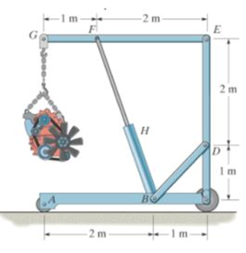
Prob. 6-81
Expert Solution & Answer

Learn your wayIncludes step-by-step video

schedule11:07
Students have asked these similar questions
Problem 3.30
A piston-cylinder device contains 0.85 kg of refrigerant- 134a at -10°C. The piston that is free to move has a mass of 12 kg and a diameter of 25 cm. The local atmospheric pressure is 100 kPa. Now, heat is transferred to refrigerant-134a until the temperature is 15°C. Determine (a) the final pressure, (b) the change in the volume of the refrigerant, and (c) the change in the enthalpy of the refrigerant-134a.
please show Al work step by step
Part 1
The storage tank contains lubricating oil of specific gravity 0.86 In one inclined side of the tank,
there is a 0.48 m diameter circular inspection door, mounted on a horizontal shaft along the centre
line of the gate. The oil level in the tank rests 8.8 m above the mounted shaft. (Please refer table
01 for relevant SG, D and h values).
Describe the hydrostatic force and centre of pressure with the aid of a free body diagram of the
inspection door.
Calculate the magnitude of the hydrostatic force and locate the centre
of pressure.
45°
Estimate the moment that would have to be applied to the shaft to
open the gate.
Stop
B
If the oil level raised by 2 m from the current level, calculate the new
moment required to open the gate.
Figure 01
From thermodynamics
please fill in the table show all work step by step
Chapter 6 Solutions
INTERNATIONAL EDITION---Engineering Mechanics: Statics, 14th edition (SI unit)
Ch. 6.3 - In each case, calculate the support reactions and...Ch. 6.3 - Identify the zero-force members in each truss....Ch. 6.3 - State if the members are in tension or...Ch. 6.3 - State if the members are in tension or...Ch. 6.3 - State if the members are in tension or...Ch. 6.3 - Determine the greatest load P that can be applied...Ch. 6.3 - Identify the zero-force members in the truss....Ch. 6.3 - State if the members are in tension or...Ch. 6.3 - Set P1 = 20 kN, P2 = 10 kN. Probs. 6-1/2Ch. 6.3 - Set P1 = 45 kN, P2 = 30 kN. Probs. 6-1/2
Ch. 6.3 - State if the members are in tension or...Ch. 6.3 - Determine the force in each member of the truss...Ch. 6.3 - Determine the force in each member of the truss,...Ch. 6.3 - Determine the force in each member of the truss,...Ch. 6.3 - Determine the force in each member of the truss...Ch. 6.3 - Determine the force in each member of the truss...Ch. 6.3 - Determine the force in each member of the truss...Ch. 6.3 - Set P1 = 6 kN, P2 = 9 kN. Probs. 6-9/10Ch. 6.3 - Determine the force in each member of the Pratt...Ch. 6.3 - Determine the force in each member of the truss...Ch. 6.3 - Determine the force in each member of the truss in...Ch. 6.3 - Members AB and BC can each support a maximum...Ch. 6.3 - If a = 6 ft, determine the greatest load P the...Ch. 6.3 - State whether the members are in tension or...Ch. 6.3 - If the maximum force that any member can support...Ch. 6.3 - Set P1 = 10 kN, P2 = 8 kN. Probs. 6-18/19Ch. 6.3 - Determine the force in each member of the truss...Ch. 6.3 - Set P1 = 9 kN, P2 = 15 kN. Probs. 6-20/21Ch. 6.3 - Determine the force in each member of the truss...Ch. 6.3 - Determine the force in each member of the double...Ch. 6.3 - Determine the force in each member of the truss in...Ch. 6.3 - Determine the maximum magnitude of load P that can...Ch. 6.3 - Take P = 2 kN. Probs. 6-25/26Ch. 6.3 - Determine the maximum magnitude P of the two loads...Ch. 6.4 - Determine the force in members BC, CF, and FE....Ch. 6.4 - State if the members are in tension or...Ch. 6.4 - State if the members are in tension or...Ch. 6.4 - State if the members are in tension or...Ch. 6.4 - State if the members are in tension or...Ch. 6.4 - State if the members are in tension or...Ch. 6.4 - Determine the force in members DC, HC, and HI of...Ch. 6.4 - Determine the force in members ED, EH, and GH of...Ch. 6.4 - Determine the force in members HG, HE and DE of...Ch. 6.4 - Determine the force in members CD, HI, and CH of...Ch. 6.4 - State if these members are in tension or...Ch. 6.4 - State if these members are in tension or...Ch. 6.4 - Determine the force in members GF, CD, and GC, and...Ch. 6.4 - Determine the force in members GH, BC, and BG of...Ch. 6.4 - Determine the force in members EF, CF, and BC, and...Ch. 6.4 - Determine the force in members AF, BF, and BC, and...Ch. 6.4 - State if these members are in tension or...Ch. 6.4 - Determine the force in members CD, CF, and CG and...Ch. 6.4 - Determine the force developed in members FE, EB,...Ch. 6.4 - Determine the force in members BC, HC, and HG....Ch. 6.4 - Determine the force in members CD, CJ, GJ, and CG...Ch. 6.4 - Determine the force in members BE, EF, and CB, and...Ch. 6.4 - Determine the force in members BF, BG, and AB, and...Ch. 6.4 - Determine the force in members BC, CH, GH, and CG...Ch. 6.4 - Determine the force in members CD, CJ, and KJ and...Ch. 6.4 - Determine the force in members JK, CJ, and CD of...Ch. 6.4 - Determine the force in members HI, FI, and EF of...Ch. 6.6 - In each case, identify any two-force members, and...Ch. 6.6 - Determine the force P needed to hold the 60-lb...Ch. 6.6 - Determine the horizontal and vertical components...Ch. 6.6 - If a 100-N force is applied to the handles of the...Ch. 6.6 - Determine the horizontal and vertical components...Ch. 6.6 - Determine the normal force that the 100-lb plate A...Ch. 6.6 - Also, determine the proper placement x of the hook...Ch. 6.6 - Determine the components of reaction at A and B....Ch. 6.6 - Determine the reactions at D. Prob. F6-20Ch. 6.6 - Determine the components of reaction at A and C....Ch. 6.6 - Determine the components of reaction at C. Prob....Ch. 6.6 - Determine the components of reaction at E. Prob....Ch. 6.6 - Determine the components of reaction at D and the...Ch. 6.6 - Determine the force P required to hold the 100-lb...Ch. 6.6 - The block weighs 100 lb. Prob. 6-62Ch. 6.6 - Determine the force P required to hold the 50-kg...Ch. 6.6 - Determine the force P required to hold the 150-kg...Ch. 6.6 - Determine the horizontal and vertical components...Ch. 6.6 - Determine the horizontal and vertical components...Ch. 6.6 - Also, what are the horizontal and vertical...Ch. 6.6 - Determine the horizontal and vertical components...Ch. 6.6 - Determine the reactions at supports A and B. Prob....Ch. 6.6 - The suspended cylinder has a mass of 75 kg. Prob....Ch. 6.6 - Determine the reactions at the supports A, C, and...Ch. 6.6 - Determine the resultant force at pins A, B, and C...Ch. 6.6 - Determine the reactions at the supports at A, E,...Ch. 6.6 - Determine the horizontal and vertical components...Ch. 6.6 - Determine the horizontal and vertical components...Ch. 6.6 - Determine the horizontal and vertical components...Ch. 6.6 - Determine the horizontal and vertical components...Ch. 6.6 - There is a hinge (pin) at D. Determine the...Ch. 6.6 - Determine the force P exerted on each of the...Ch. 6.6 - The toggle clamp is subjected to a force F at the...Ch. 6.6 - Determine the force the load creates in member DB...Ch. 6.6 - Determine the compressive force developed on the...Ch. 6.6 - Also, find the horizontal and vertical components...Ch. 6.6 - Also, what are the horizontal and vertical...Ch. 6.6 - Determine the force in the guy cable AI and the...Ch. 6.6 - When the walking beam ABC is horizontal, the force...Ch. 6.6 - Determine the force that the jaws J of the metal...Ch. 6.6 - It consists of two toggles ABC and DBF, which are...Ch. 6.6 - The 600-N load is applied to the pin. Prob. 6-89Ch. 6.6 - If the wheel at A exerts a normal force of FA = 80...Ch. 6.6 - The shovel load has a mass of 1.25 Mg and a center...Ch. 6.6 - Determine the horizontal and vertical components...Ch. 6.6 - Determine the compressive force P that is exerted...Ch. 6.6 - If each coin weighs 0.0235 lb, determine the...Ch. 6.6 - Assuming the blades are pin connected at B and the...Ch. 6.6 - Determine the total force he must exert on bar AB...Ch. 6.6 - Determine the total force he must exert on bar AB...Ch. 6.6 - The cable is attached to D, passes over the smooth...Ch. 6.6 - The grip at B on member DAB resists both...Ch. 6.6 - If the compression in the spring is 20 mm when the...Ch. 6.6 - If a clamping force of 300 N is required at A,...Ch. 6.6 - If a force of F = 350 N is applied to the handle...Ch. 6.6 - Determine the horizontal and vertical components...Ch. 6.6 - Determine the force in the hydraulic cylinder AB...Ch. 6.6 - The spring has a stiffness of k = 6 kN/m. Prob....Ch. 6.6 - If d = 0.75 ft and the spring has an unstretched...Ch. 6.6 - If a force of F = 50 lb is applied to the pads at...Ch. 6.6 - If there is a 300-kg stone in the bucket, with...Ch. 6.6 - when the mechanism is in the position shown. The...Ch. 6.6 - Prob. 110PCh. 6.6 - Prob. 111PCh. 6.6 - If the sprig has a stiffness of k = 15 lb/in., and...Ch. 6.6 - Through this arrangement, a small weight can...Ch. 6.6 - Through this arrangement, a small weight can...Ch. 6.6 - If only vertical forces are supported at the...Ch. 6.6 - Determine the force in each member of the truss...Ch. 6.6 - Determine the force in each member of the truss...Ch. 6.6 - Determine the force in member GJ and GC of the...Ch. 6.6 - Determine the force in members GF, FB, and BC of...Ch. 6.6 - Determine the horizontal and vertical components...Ch. 6.6 - Determine the horizontal and vertical components...Ch. 6.6 - Determine the resultant forces at pins B and C on...
Additional Engineering Textbook Solutions
Find more solutions based on key concepts
In Exercises 55 through 60, find the value of the given function where a and b are numeric variables of type Do...
Introduction To Programming Using Visual Basic (11th Edition)
Why does an oxyfuel-gas welding torch usually have a flame with two distinct regions?
Degarmo's Materials And Processes In Manufacturing
1.1 List 10 uses. for surveying in areas other than land
sunreying-
Elementary Surveying: An Introduction To Geomatics (15th Edition)
Average of Numbers Assume that a file containing a series of integers is named numbers.dat and exists on the co...
Starting Out with Programming Logic and Design (5th Edition) (What's New in Computer Science)
For each of the following numeric formats, identify the format string used as the input parameter when calling ...
Starting Out With Visual Basic (8th Edition)
Payroll Class Design a PayRoll class that has data members for an employees hourly pay rate, number of hours wo...
Starting Out with C++ from Control Structures to Objects (9th Edition)
Knowledge Booster


Learn more about
Need a deep-dive on the concept behind this application? Look no further. Learn more about this topic, mechanical-engineering and related others by exploring similar questions and additional content below.Similar questions
- The 150-lb skater passes point A with a speed of 6 ft/s. (Figure 1) Determine his speed when he reaches point B. Neglect friction. Determine the normal force exerted on him by the track at this point. 25 ft B = 4x A 20 ft xarrow_forwardA virtual experiment is designed to determine the effect of friction on the timing and speed of packages being delivered to a conveyor belt and the normal force applied to the tube. A package is held and then let go at the edge of a circular shaped tube of radius R = 5m. The particle at the bottom will transfer to the conveyor belt, as shown below. Run the simulations for μ = 0, 0.1, 0.2, 0.3, 0.4, 0.5, 0.6 and determine the time and speed at which the package is delivered to the conveyor belt. In addition, determine the maximum normal force and its location along the path as measured by angle 0. Submit in hardcopy form: (0) Free Body Diagram, equations underneath, derivations (a) Your MATLAB mfile (b) A table listing the values in 5 columns: μ, T (time of transfer), V (speed of transfer), 0 (angle of max N), Nmax (max N) (c) Based on your results, explain in one sentence what you think will happen to the package if the friction is increased even further, e.g. μ = 0.8. NOTE: The ODE is…arrow_forwardPatm = 1 bar Piston m = 50 kg 5 g of Air T₁ = 600 K P₁ = 3 bar Stops A 9.75 x 10⁻³ m² FIGURE P3.88arrow_forward
- Assume a Space Launch System (Figure 1(a)) that is approximated as a cantilever undamped single degree of freedom (SDOF) system with a mass at its free end (Figure 1(b)). The cantilever is assumed to be massless. Assume a wind load that is approximated with a concentrated harmonic forcing function p(t) = posin(ωt) acting on the mass. The known properties of the SDOF and the applied forcing function are given below. • Mass of SDOF: m =120 kip/g • Acceleration of gravity: g = 386 in/sec2 • Bending sectional stiffness of SDOF: EI = 1015 lbf×in2 • Height of SDOF: h = 2000 inches • Amplitude of forcing function: po = 6 kip • Forcing frequency: f = 8 Harrow_forwardAssume a Space Launch System (Figure 1(a)) that is approximated as a cantilever undamped single degree of freedom (SDOF) system with a mass at its free end (Figure 1(b)). The cantilever is assumed to be massless. Assume a wind load that is approximated with a concentrated harmonic forcing function p(t) = posin(ωt) acting on the mass. The known properties of the SDOF and the applied forcing function are given below. • Mass of SDOF: m =120 kip/g • Acceleration of gravity: g = 386 in/sec2 • Bending sectional stiffness of SDOF: EI = 1015 lbf×in2 • Height of SDOF: h = 2000 inches • Amplitude of forcing function: po = 6 kip • Forcing frequency: f = 8 Hz Figure 1: Single-degree-of-freedom system in Problem 1. Please compute the following considering the steady-state response of the SDOF system. Do not consider the transient response unless it is explicitly stated in the question. (a) The natural circular frequency and the natural period of the SDOF. (10 points) (b) The maximum displacement of…arrow_forwardAssume a Space Launch System (Figure 1(a)) that is approximated as a cantilever undamped single degree of freedom (SDOF) system with a mass at its free end (Figure 1(b)). The cantilever is assumed to be massless. Assume a wind load that is approximated with a concentrated harmonic forcing function p(t) = posin(ωt) acting on the mass. The known properties of the SDOF and the applied forcing function are given below. • Mass of SDOF: m =120 kip/g • Acceleration of gravity: g = 386 in/sec2 • Bending sectional stiffness of SDOF: EI = 1015 lbf×in2 • Height of SDOF: h = 2000 inches • Amplitude of forcing function: po = 6 kip • Forcing frequency: f = 8 Hz Figure 1: Single-degree-of-freedom system in Problem 1. Please compute the following considering the steady-state response of the SDOF system. Do not consider the transient response unless it is explicitly stated in the question. (a) The natural circular frequency and the natural period of the SDOF. (10 points) (b) The maximum displacement of…arrow_forward
- Please solve 13 * √(2675.16)² + (63.72 + 2255,03)² = 175x106 can you explain the process for getting d seperate thank youarrow_forwardIf the 300-kg drum has a center of mass at point G, determine the horizontal and vertical components of force acting at pin A and the reactions on the smooth pads C and D. The grip at B on member DAB resists both horizontal and vertical components of force at the rim of the drum. P 60 mm; 60 mm: 600 mm A E 30° B C 390 mm 100 mm D Garrow_forwardThe design of the gear-and-shaft system shown requires that steel shafts of the same diameter be used for both AB and CD. It is further required that the angle D through which end D of shaft CD rotates not exceed 1.5°. Knowing that G = 77.2 GPa, determine the required diameter of the shafts. 40 mm 400 mm 100 mm 600 mm T-1000 N-m Darrow_forward
- Assume a Space Launch System (Figure 1(a)) that is approximated as a cantilever undamped single degree of freedom (SDOF) system with a mass at its free end (Figure 1(b)). The cantilever is assumed to be massless. Assume a wind load that is approximated with a concentrated harmonic forcing function p(t) = posin(ωt) acting on the mass. The known properties of the SDOF and the applied forcing function are given below. • Mass of SDOF: m =120 kip/g • Acceleration of gravity: g = 386 in/sec2 • Bending sectional stiffness of SDOF: EI = 1015 lbf×in2 • Height of SDOF: h = 2000 inches • Amplitude of forcing function: po = 6 kip • Forcing frequency: f = 8 Hzarrow_forward13.44 The end of a cylindrical liquid cryogenic propellant tank in free space is to be protected from external (solar) radiation by placing a thin metallic shield in front of the tank. Assume the view factor Fts between the tank and the shield is unity; all surfaces are diffuse and gray, and the surroundings are at 0 K. Tank T₁ Shield, T T₁ = 100 K E1 Solar irradiation Gs ε₁ = ε₂ = 0.05 ε₁ = 0.10 Gs = 1250 W/m² E2 Find the temperature of the shield T, and the heat flux (W/m²) to the end of the tank.arrow_forwardquestion 664 thank youarrow_forward
arrow_back_ios
SEE MORE QUESTIONS
arrow_forward_ios
Recommended textbooks for you
 Elements Of ElectromagneticsMechanical EngineeringISBN:9780190698614Author:Sadiku, Matthew N. O.Publisher:Oxford University Press
 Mechanics of Materials (10th Edition)Mechanical EngineeringISBN:9780134319650Author:Russell C. HibbelerPublisher:PEARSON
 Thermodynamics: An Engineering ApproachMechanical EngineeringISBN:9781259822674Author:Yunus A. Cengel Dr., Michael A. BolesPublisher:McGraw-Hill Education
 Control Systems EngineeringMechanical EngineeringISBN:9781118170519Author:Norman S. NisePublisher:WILEY
 Mechanics of Materials (MindTap Course List)Mechanical EngineeringISBN:9781337093347Author:Barry J. Goodno, James M. GerePublisher:Cengage Learning
 Engineering Mechanics: StaticsMechanical EngineeringISBN:9781118807330Author:James L. Meriam, L. G. Kraige, J. N. BoltonPublisher:WILEY
Elements Of Electromagnetics
Mechanical Engineering
ISBN:9780190698614
Author:Sadiku, Matthew N. O.
Publisher:Oxford University Press
Mechanics of Materials (10th Edition)
Mechanical Engineering
ISBN:9780134319650
Author:Russell C. Hibbeler
Publisher:PEARSON
Thermodynamics: An Engineering Approach
Mechanical Engineering
ISBN:9781259822674
Author:Yunus A. Cengel Dr., Michael A. Boles
Publisher:McGraw-Hill Education
Control Systems Engineering
Mechanical Engineering
ISBN:9781118170519
Author:Norman S. Nise
Publisher:WILEY
Mechanics of Materials (MindTap Course List)
Mechanical Engineering
ISBN:9781337093347
Author:Barry J. Goodno, James M. Gere
Publisher:Cengage Learning
Engineering Mechanics: Statics
Mechanical Engineering
ISBN:9781118807330
Author:James L. Meriam, L. G. Kraige, J. N. Bolton
Publisher:WILEY
Mechanical SPRING DESIGN Strategy and Restrictions in Under 15 Minutes!; Author: Less Boring Lectures;https://www.youtube.com/watch?v=dsWQrzfQt3s;License: Standard Youtube License