
INTERNATIONAL EDITION---Engineering Mechanics: Statics, 14th edition (SI unit)
14th Edition
ISBN: 9780133918922
Author: Russell C. Hibbeler
Publisher: PEARSON
expand_more
expand_more
format_list_bulleted
Concept explainers
Videos
Textbook Question
Chapter 6.4, Problem 40P
Determine the force in members CD, CF, and CG and state if these members are in tension or compression.
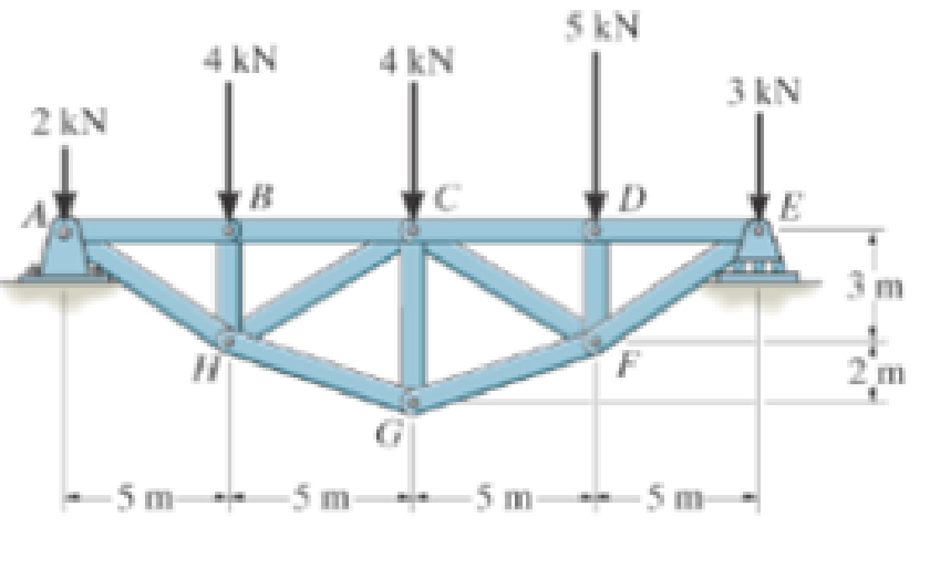
Probs. 6-39/40
Expert Solution & Answer

Learn your wayIncludes step-by-step video

schedule10:05
Students have asked these similar questions
نصاف
Sheet
Asteel bar of rectangular cross section with
dimension
Shown in fig. below. This bar is
as
Connected toawell. Using welded Join a long the sides
als only find the weld size (h). Where:
Tall = 35 MN/M²
F=213.30
answer/h=
4.04
☐
Yomm
Soomm
100mm
FEA
FEA
Chapter 6 Solutions
INTERNATIONAL EDITION---Engineering Mechanics: Statics, 14th edition (SI unit)
Ch. 6.3 - In each case, calculate the support reactions and...Ch. 6.3 - Identify the zero-force members in each truss....Ch. 6.3 - State if the members are in tension or...Ch. 6.3 - State if the members are in tension or...Ch. 6.3 - State if the members are in tension or...Ch. 6.3 - Determine the greatest load P that can be applied...Ch. 6.3 - Identify the zero-force members in the truss....Ch. 6.3 - State if the members are in tension or...Ch. 6.3 - Set P1 = 20 kN, P2 = 10 kN. Probs. 6-1/2Ch. 6.3 - Set P1 = 45 kN, P2 = 30 kN. Probs. 6-1/2
Ch. 6.3 - State if the members are in tension or...Ch. 6.3 - Determine the force in each member of the truss...Ch. 6.3 - Determine the force in each member of the truss,...Ch. 6.3 - Determine the force in each member of the truss,...Ch. 6.3 - Determine the force in each member of the truss...Ch. 6.3 - Determine the force in each member of the truss...Ch. 6.3 - Determine the force in each member of the truss...Ch. 6.3 - Set P1 = 6 kN, P2 = 9 kN. Probs. 6-9/10Ch. 6.3 - Determine the force in each member of the Pratt...Ch. 6.3 - Determine the force in each member of the truss...Ch. 6.3 - Determine the force in each member of the truss in...Ch. 6.3 - Members AB and BC can each support a maximum...Ch. 6.3 - If a = 6 ft, determine the greatest load P the...Ch. 6.3 - State whether the members are in tension or...Ch. 6.3 - If the maximum force that any member can support...Ch. 6.3 - Set P1 = 10 kN, P2 = 8 kN. Probs. 6-18/19Ch. 6.3 - Determine the force in each member of the truss...Ch. 6.3 - Set P1 = 9 kN, P2 = 15 kN. Probs. 6-20/21Ch. 6.3 - Determine the force in each member of the truss...Ch. 6.3 - Determine the force in each member of the double...Ch. 6.3 - Determine the force in each member of the truss in...Ch. 6.3 - Determine the maximum magnitude of load P that can...Ch. 6.3 - Take P = 2 kN. Probs. 6-25/26Ch. 6.3 - Determine the maximum magnitude P of the two loads...Ch. 6.4 - Determine the force in members BC, CF, and FE....Ch. 6.4 - State if the members are in tension or...Ch. 6.4 - State if the members are in tension or...Ch. 6.4 - State if the members are in tension or...Ch. 6.4 - State if the members are in tension or...Ch. 6.4 - State if the members are in tension or...Ch. 6.4 - Determine the force in members DC, HC, and HI of...Ch. 6.4 - Determine the force in members ED, EH, and GH of...Ch. 6.4 - Determine the force in members HG, HE and DE of...Ch. 6.4 - Determine the force in members CD, HI, and CH of...Ch. 6.4 - State if these members are in tension or...Ch. 6.4 - State if these members are in tension or...Ch. 6.4 - Determine the force in members GF, CD, and GC, and...Ch. 6.4 - Determine the force in members GH, BC, and BG of...Ch. 6.4 - Determine the force in members EF, CF, and BC, and...Ch. 6.4 - Determine the force in members AF, BF, and BC, and...Ch. 6.4 - State if these members are in tension or...Ch. 6.4 - Determine the force in members CD, CF, and CG and...Ch. 6.4 - Determine the force developed in members FE, EB,...Ch. 6.4 - Determine the force in members BC, HC, and HG....Ch. 6.4 - Determine the force in members CD, CJ, GJ, and CG...Ch. 6.4 - Determine the force in members BE, EF, and CB, and...Ch. 6.4 - Determine the force in members BF, BG, and AB, and...Ch. 6.4 - Determine the force in members BC, CH, GH, and CG...Ch. 6.4 - Determine the force in members CD, CJ, and KJ and...Ch. 6.4 - Determine the force in members JK, CJ, and CD of...Ch. 6.4 - Determine the force in members HI, FI, and EF of...Ch. 6.6 - In each case, identify any two-force members, and...Ch. 6.6 - Determine the force P needed to hold the 60-lb...Ch. 6.6 - Determine the horizontal and vertical components...Ch. 6.6 - If a 100-N force is applied to the handles of the...Ch. 6.6 - Determine the horizontal and vertical components...Ch. 6.6 - Determine the normal force that the 100-lb plate A...Ch. 6.6 - Also, determine the proper placement x of the hook...Ch. 6.6 - Determine the components of reaction at A and B....Ch. 6.6 - Determine the reactions at D. Prob. F6-20Ch. 6.6 - Determine the components of reaction at A and C....Ch. 6.6 - Determine the components of reaction at C. Prob....Ch. 6.6 - Determine the components of reaction at E. Prob....Ch. 6.6 - Determine the components of reaction at D and the...Ch. 6.6 - Determine the force P required to hold the 100-lb...Ch. 6.6 - The block weighs 100 lb. Prob. 6-62Ch. 6.6 - Determine the force P required to hold the 50-kg...Ch. 6.6 - Determine the force P required to hold the 150-kg...Ch. 6.6 - Determine the horizontal and vertical components...Ch. 6.6 - Determine the horizontal and vertical components...Ch. 6.6 - Also, what are the horizontal and vertical...Ch. 6.6 - Determine the horizontal and vertical components...Ch. 6.6 - Determine the reactions at supports A and B. Prob....Ch. 6.6 - The suspended cylinder has a mass of 75 kg. Prob....Ch. 6.6 - Determine the reactions at the supports A, C, and...Ch. 6.6 - Determine the resultant force at pins A, B, and C...Ch. 6.6 - Determine the reactions at the supports at A, E,...Ch. 6.6 - Determine the horizontal and vertical components...Ch. 6.6 - Determine the horizontal and vertical components...Ch. 6.6 - Determine the horizontal and vertical components...Ch. 6.6 - Determine the horizontal and vertical components...Ch. 6.6 - There is a hinge (pin) at D. Determine the...Ch. 6.6 - Determine the force P exerted on each of the...Ch. 6.6 - The toggle clamp is subjected to a force F at the...Ch. 6.6 - Determine the force the load creates in member DB...Ch. 6.6 - Determine the compressive force developed on the...Ch. 6.6 - Also, find the horizontal and vertical components...Ch. 6.6 - Also, what are the horizontal and vertical...Ch. 6.6 - Determine the force in the guy cable AI and the...Ch. 6.6 - When the walking beam ABC is horizontal, the force...Ch. 6.6 - Determine the force that the jaws J of the metal...Ch. 6.6 - It consists of two toggles ABC and DBF, which are...Ch. 6.6 - The 600-N load is applied to the pin. Prob. 6-89Ch. 6.6 - If the wheel at A exerts a normal force of FA = 80...Ch. 6.6 - The shovel load has a mass of 1.25 Mg and a center...Ch. 6.6 - Determine the horizontal and vertical components...Ch. 6.6 - Determine the compressive force P that is exerted...Ch. 6.6 - If each coin weighs 0.0235 lb, determine the...Ch. 6.6 - Assuming the blades are pin connected at B and the...Ch. 6.6 - Determine the total force he must exert on bar AB...Ch. 6.6 - Determine the total force he must exert on bar AB...Ch. 6.6 - The cable is attached to D, passes over the smooth...Ch. 6.6 - The grip at B on member DAB resists both...Ch. 6.6 - If the compression in the spring is 20 mm when the...Ch. 6.6 - If a clamping force of 300 N is required at A,...Ch. 6.6 - If a force of F = 350 N is applied to the handle...Ch. 6.6 - Determine the horizontal and vertical components...Ch. 6.6 - Determine the force in the hydraulic cylinder AB...Ch. 6.6 - The spring has a stiffness of k = 6 kN/m. Prob....Ch. 6.6 - If d = 0.75 ft and the spring has an unstretched...Ch. 6.6 - If a force of F = 50 lb is applied to the pads at...Ch. 6.6 - If there is a 300-kg stone in the bucket, with...Ch. 6.6 - when the mechanism is in the position shown. The...Ch. 6.6 - Prob. 110PCh. 6.6 - Prob. 111PCh. 6.6 - If the sprig has a stiffness of k = 15 lb/in., and...Ch. 6.6 - Through this arrangement, a small weight can...Ch. 6.6 - Through this arrangement, a small weight can...Ch. 6.6 - If only vertical forces are supported at the...Ch. 6.6 - Determine the force in each member of the truss...Ch. 6.6 - Determine the force in each member of the truss...Ch. 6.6 - Determine the force in member GJ and GC of the...Ch. 6.6 - Determine the force in members GF, FB, and BC of...Ch. 6.6 - Determine the horizontal and vertical components...Ch. 6.6 - Determine the horizontal and vertical components...Ch. 6.6 - Determine the resultant forces at pins B and C on...
Additional Engineering Textbook Solutions
Find more solutions based on key concepts
What is the importance of modeling in engineering? How are the mathematical models for engineering processes pr...
HEAT+MASS TRANSFER:FUND.+APPL.
Big data Big data describes datasets with huge volumes that are beyond the ability of typical database manageme...
Management Information Systems: Managing The Digital Firm (16th Edition)
a. What single instruction in the Vole machine language could be used to accomplish a 5-bit right circular shif...
Computer Science: An Overview (13th Edition) (What's New in Computer Science)
Look at the following code: String str1 = To be, or not to be; String str2 = str1.replace(o, u); System.out.pri...
Starting Out with Java: From Control Structures through Data Structures (4th Edition) (What's New in Computer Science)
When working with a sequential access file, you can jump directly to any piece of data in the file without read...
Starting Out with Programming Logic and Design (5th Edition) (What's New in Computer Science)
Figure 1-30 shows the Visual Studio IDE. What are the names of the four areas indicated in the figure? Figure 1...
Starting Out With Visual Basic (8th Edition)
Knowledge Booster


Learn more about
Need a deep-dive on the concept behind this application? Look no further. Learn more about this topic, mechanical-engineering and related others by exploring similar questions and additional content below.Similar questions
- HELP?arrow_forwardTrue and False Indicate if each statement is true or false. T/F 1. Rule #1 protects the function of assembly. T/F 2. One of the fundamental dimensioning rules requires all dimensions apply in the free-state condition for rigid parts. T/F 3. The fundamental dimensioning rules that apply on a drawing must be listed in the general notes. T/F 4. Where Rule #1 applies to a drawing, it limits the form of every feature of size on the drawing. T/F 5. Rule #1 limits the variation between features of size on a part. T/F 6. The designer must specify on the drawing which features of size use Rule #1. T/F T/F T/F 7. Rule #1 applies to nonrigid parts (in the unrestrained state). 8. A GO gage is a fixed-limit gage. 9. Rule #1 requires that the form of an individual regular feature of size is controlled by its limits of sizearrow_forwardFEAarrow_forward
- Please also draw the FBDsarrow_forwardDesign Description: Fresh water tank, immersed in an oil tank.a) Water tank:a. Shape: Cylindricalb. Radius: 1 meterc. Height: 3 metersd. Bottom airlock: 0.2m x 0.2m. b) Oil tank:a. Shape: cylindricalb. Radius: 4 metersc. Oil density: 850 kg/m³ Determine:a) The pressure experienced by an airlock at the bottom of the tank with water.b) The force and direction necessary to open the lock, suppose the lock weighs 20 Newtons, suppose the lock opens outwards. The image is for illustrative purposes, the immersed cylinder does not reach the bottomarrow_forwardNeed help!arrow_forward
arrow_back_ios
SEE MORE QUESTIONS
arrow_forward_ios
Recommended textbooks for you
 Elements Of ElectromagneticsMechanical EngineeringISBN:9780190698614Author:Sadiku, Matthew N. O.Publisher:Oxford University Press
 Mechanics of Materials (10th Edition)Mechanical EngineeringISBN:9780134319650Author:Russell C. HibbelerPublisher:PEARSON
 Thermodynamics: An Engineering ApproachMechanical EngineeringISBN:9781259822674Author:Yunus A. Cengel Dr., Michael A. BolesPublisher:McGraw-Hill Education
 Control Systems EngineeringMechanical EngineeringISBN:9781118170519Author:Norman S. NisePublisher:WILEY
 Mechanics of Materials (MindTap Course List)Mechanical EngineeringISBN:9781337093347Author:Barry J. Goodno, James M. GerePublisher:Cengage Learning
 Engineering Mechanics: StaticsMechanical EngineeringISBN:9781118807330Author:James L. Meriam, L. G. Kraige, J. N. BoltonPublisher:WILEY
Elements Of Electromagnetics
Mechanical Engineering
ISBN:9780190698614
Author:Sadiku, Matthew N. O.
Publisher:Oxford University Press
Mechanics of Materials (10th Edition)
Mechanical Engineering
ISBN:9780134319650
Author:Russell C. Hibbeler
Publisher:PEARSON
Thermodynamics: An Engineering Approach
Mechanical Engineering
ISBN:9781259822674
Author:Yunus A. Cengel Dr., Michael A. Boles
Publisher:McGraw-Hill Education
Control Systems Engineering
Mechanical Engineering
ISBN:9781118170519
Author:Norman S. Nise
Publisher:WILEY
Mechanics of Materials (MindTap Course List)
Mechanical Engineering
ISBN:9781337093347
Author:Barry J. Goodno, James M. Gere
Publisher:Cengage Learning
Engineering Mechanics: Statics
Mechanical Engineering
ISBN:9781118807330
Author:James L. Meriam, L. G. Kraige, J. N. Bolton
Publisher:WILEY
Engineering Basics - Statics & Forces in Equilibrium; Author: Solid Solutions - Professional Design Solutions;https://www.youtube.com/watch?v=dQBvQ2hJZFg;License: Standard YouTube License, CC-BY