
Concept explainers
Videos
Two shafts AC and CF, which lie in the vertical xy plane, are connected by a universal joint at C. The bearings at B and D do not exert any axial force. A couple with a magnitude of 500 lb·in. (clockwise when viewed from the positive x axis) is applied to shaft CF at F. At a time when the arm of the crosspiece attached to shaft CF is horizontal, determine (a) the magnitude of the couple that must be applied to shaft AC at A to maintain equilibrium, (b) the reactions at B, D, and E. (Hint: The sum of the couples exerted on the crosspiece must be zero.)
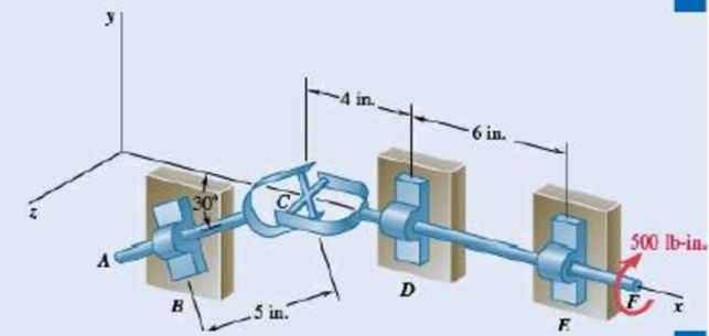
Fig. P6.161
*6.162 Solve Prob. 6.161 assuming that the arm of the crosspiece attached to shaft CF is vertical.
(a)
The magnitude of the couple that must be applied to shaft
Answer to Problem 6.162P
The magnitude of the couple that must be applied to shaft
Explanation of Solution
Take all vectors along the
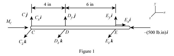
The free body diagram of the shaft
Here,
At equilibrium total moment will be zero.
Write the expression for the equilibrium moment about
Here,
The moment along the
From free body diagram in figure1, write the complete equilibrium expression of moment about
 (II)
(II)
Here,
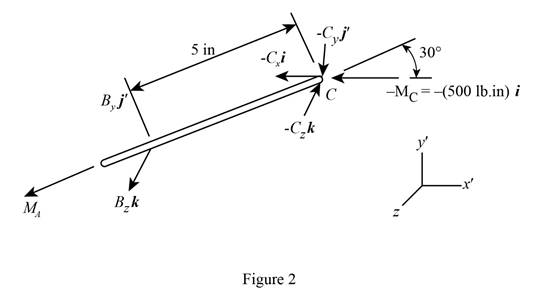
The free body diagram of the shaft
Here,
Write the expression for the equilibrium moment about
Here,
Resolve
From free body diagram in figure2, write the complete equilibrium expression of moment about
Here,
Calculation:
Rearrange equation (II) to get
Equate coefficient of
Therefore, the magnitude of the couple that must be applied to shaft
(b)
The reaction at
Answer to Problem 6.162P
The reaction at
Explanation of Solution
From free body diagram in figure2, write the complete equilibrium expression of moment about
Here,
Since the net force at the shaft
Using free body diagram in figure1, apply the equilibrium condition for moment about
Here,
From figure1, write the complete expression of moment
Since net force at shaft
Calculation:
Equate coefficient of
Equate coefficient of
Therefore,
Substitute
Equate coefficient of
Equate coefficient of
Equate coefficient of
Therefore, net reaction at
Substitute
Equate coefficient of
Therefore, total reaction at
Therefore, the reaction at
Want to see more full solutions like this?
Chapter 6 Solutions
Connect 1 Semester Access Card for Vector Mechanics for Engineers: Statics and Dynamics


- Question 2 (40 Points) Consider the following double pendulum-like system with links ₁ and 12. The angles 0 and & could have angular velocities ėêk and êk, respectively, where ②k is a unit vector that points out of the page and is perpendicular to x and y. They could also have angular accelerations Ök and êk. The angle is defined relative to the angle 0. The link 12 is a spring and can extend or compress at a rate of 12. It can also have a rate of extension or compression Ï2. li y êr1 êe 12 χ 3 еф er2 ده لج 1) Express the velocity of the mass in terms of the unit vectors ê0, êr1, êø, and êr2, and any extension/contraction of the links (e.g.,. i; and Ï¿) (12 Points) 2) Express the acceleration of the mass in terms of the unit vectors ê¤, ê×1, êp, and êÃ2, and any extension/contraction of the links (e.g.,. İ; and Ï¿) (12 Points) 3) Express the velocity of the mass in terms of unit vectors î and ĵ that point in the x and y directions, respectively. Also include the appropriate,…arrow_forwardprovide step by step solutions for angles teta 3 and teta 4 by the vector loopmethod. Show work in: vector loop, vector equations, solution procedure.arrow_forward(Manometer) A tank is constructed of a series of cylinders having diameters of 0.35, 0.30, and 0.20 m as shown in the figure below. The tank contains oil, water, and glycerin and a mercury manometer is attached to the bottom as illustrated. Calculate the manometer reading, h. 0.11 m + SAE 30 Oil 0.13 m + Water 0.10 m Glycerin + 0.10 m Mercury h = marrow_forward
- P = A piston having a cross-sectional area of 0.40 m² is located in a cylinder containing water as shown in the figure below. An open U-tube manometer is connected to the cylinder as shown. For h₁ = 83 mm and h = 111 mm what is the value of the applied force, P, acting on the piston? The weight of the piston is negligible. Hi 5597.97 N P Piston Water Mercuryarrow_forwardStudent Name: Student Id: College of Applied Engineering Al-Muzahmiyah Branch Statics (AGE 1330) Section-1483 Quiz-2 Time: 20 minutes Date: 16/02/2025 Q.1. A swinging door that weighs w=400.0N is supported by hinges A and B so that the door can swing about a vertical' axis passing through the hinges (as shown in below figure). The door has a width of b=1.00m and the door slab has a uniform mass density. The hinges are placed symmetrically at the door's edge in such a way that the door's weight is evenly distributed between them. The hinges are separated by distance a=2.00m. Find the forces on the hinges when the door rests half-open. Draw Free body diagram also. [5 marks] [CLO 1.2] Mool b ర a 2.0 m B 1.0 marrow_forwardFor the walking-beam mechanism shown in Figure 3, find and plot the x and y coordinates of the position of the coupler point P for one complete revolution of the crank O2A. Use the coordinate system shown in Figure 3. Hint: Calculate them first with respect to the ground link 0204 and then transform them into the global XY coordinate system. y -1.75 Ꮎ Ꮎ 4 = 2.33 0242.22 L4 x AP = 3.06 L2 = 1.0 W2 31° B 03 L3 = 2.06 P 1 8 5 .06 6 7 P'arrow_forward
- The link lengths, gear ratio (2), phase angle (Ø), and the value of 02 for some geared five bar linkages are defined in Table 2. The linkage configuration and terminology are shown in Figure 2. For the rows assigned, find all possible solutions for angles 03 and 04 by the vector loop method. Show your work in details: vector loop, vector equations, solution procedure. Table 2 Row Link 1 Link 2 Link 3 Link 4 Link 5 λ Φ Ө a 6 1 7 9 4 2 30° 60° P y 4 YA B b R4 R3 YA A Gear ratio: a 02 d 05 r5 R5 R2 Phase angle: = 0₂-202 R1 05 02 r2 Figure 2. 04 Xarrow_forwardProblem 4 A .025 lb bullet C is fired at end B of the 15-lb slender bar AB. The bar is initially at rest, and the initial velocity of the bullet is 1500 ft/s as shown. Assuming that the bullet becomes embedded in the bar, find (a) the angular velocity @2 of the bar immediately after impact, and (b) the percentage loss of kinetic energy as a result of the impact. (c) After the impact, does the bar swing up 90° and reach the horizontal? If it does, what is its angular velocity at this point? Answers: (a). @2=1.6 rad/s; (b). 99.6% loss = (c). Ah2 0.212 ft. The bar does not reach horizontal. y X 4 ft 15 lb V₁ 1500 ft/s 0.025 lb C 30°7 B Aarrow_forwardsubject: combustion please include complete solution, no rounding off, with diagram/explanation etc. In a joule cycle, intake of the compressor is 40,000 cfm at 0.3 psig and 90 deg F. The compression ratio is 6.0 and the inlet temperature at the turbine portion is 1900R while at the exit, it is 15 psi. Calculate for the back work ratio in percent.arrow_forward
- subject: combustion please include complete solution, no rounding off, with diagram/explanation etc. A gasoline engine, utilizing cold air, recorded a work of 431 BTU/lb at a maximum temperature of 3,273 K and 1112 deg F temperature at the beginning of constant volume heat addition. What is the compression ratio?arrow_forwardsubject: combustion please do step by step solution and no rounding off, complete solution with diagram/explanation if needed etc. thank you! Air enters the compressor at 101,320 Pascals, 305.15K, and leaves at a pressure of 0.808MPa. The air is heated to 990.15K in the combustion chamber. For a net output of 2,125,000 Watts, find the rate of flow of air per second.arrow_forwardThe link lengths and the value of 2 and offset for some fourbar crank-slide linkages are defined in Table 1. The linkage configuration and terminology are shown in Figure 1. For the rows assigned, find (a) all possible solutions for angle & and slider position d by vector loop method. (b) the transmission angle corresponding to angle 03. (Hint: Treat the vector R4 as virtual rocker) Show your work in details: vector loop, vector equations, solution procedure. Table 1 Row Link 2 Link 3 Offset Ө a 1.4 4 1 45° b 3 8 2 -30° C 5 20 -5 225° 03 slider axis B X offset Link 2 A R3 Link 3 R4 04 R2 02 R1 d Figure 1. Xarrow_forward
 International Edition---engineering Mechanics: St...Mechanical EngineeringISBN:9781305501607Author:Andrew Pytel And Jaan KiusalaasPublisher:CENGAGE L