
Concept explainers
The truss shown consists of nine members and is supported by a ball and socket at A, two short links at B, and a short link at C. Determine the force in each of the members for the given loading.
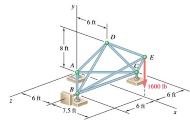
The force in each of the members of the truss for the given loading.
Answer to Problem 6.38P
The force in member
Explanation of Solution
The free-body diagram of the entire truss is shown in figure 1.
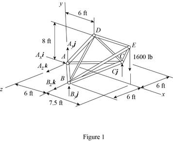
Refer to figure 1 and use symmetry.
Here,
The
Here,
Sum of the moments must be equal to zero.
Here,
Write the equation for
Here,
Put the above equation in equation (I).
Write the expression for the reaction at the point A.
Here,
Substitute
Use symmetry.
Here,
The
Here,
Write the expression for
Put the above equation in equation (II).
Write the expression for the reaction at the point A.
Here,
Substitute
Consider the free body
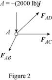
The net force must be equal to zero.
Here,
Write the expression for
Put the above equation in equation (III).
Here,
Write the expression for
Here,
Write the expression for
Here,
Write the expression for
Here,
Put equations (V), (VI) and (VII) in equation (IV).
Factorize
Equate the coefficient of
Equate the coefficient of
Equate the coefficient of
Put equation (X) in equation (IX).
Substitute
Put the above equation in equation (X).
Consider the free-body joint B. The free-body diagram of joint B is shown in figure 3.
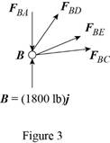
Refer to figure (3) and write the expression for the forces.
Here,
Substitute
Write the expression for
Here,
Write the expression for
Here,
Write the expression for
Here,
Substitute
Write the expression for
Put the above equation in equation (III).
Put equations (XI), (XII), (XIII) , (XIV) and substitute
Equate the coefficient of
Equate the coefficient of
Substitute
Equate the coefficient of
Substitute
Use symmetry.
Here,
Substitute
Consider the free body joint D. The free body diagram is shown in figure 4.
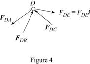
Write the expression for
Put the above equation in equation (III).
Only
Equate the coefficient of
Substitute
Conclusion:
Thus, the force in member
Want to see more full solutions like this?
Chapter 6 Solutions
Connect 1 Semester Access Card for Vector Mechanics for Engineers: Statics and Dynamics
- Can you answer this question?arrow_forwardA gear has a gear wheel with 16 teeth. The gear should be dimensioned for the highest and lowest gear ratio. Looking for output power, torque, speed?nin= 2000 rpmmin = 30Nmn=0,9a max= 450 mmModule 4Gear limitsz1 z213 13-1614 14-2615 15-4516 16-10117 17-131418 18-…..I have calculate but I can’t get the right answers…..√16 =459x60/56x57=1.1 lowest59x60/13x13=20,94 highestnut=2000/1.1= 1818rpmnut=2000/20.94=95.5 rpmMut=1.1x30=33 NmMut=20.94x30=628,2 Nm(Right answer)LowestZ=13, M=24,4Nm, n=2462 rpmHighestZ=92, M=172,5Nm, n=347,8 rpmP=5655W on botharrow_forwardPlease see attached pic.arrow_forward
 International Edition---engineering Mechanics: St...Mechanical EngineeringISBN:9781305501607Author:Andrew Pytel And Jaan KiusalaasPublisher:CENGAGE L
