
Concept explainers
Find the equations for slope and deflection of the beam using direct integration method.
Answer to Problem 1P
The equation for slope is
The equation for deflection is
Explanation of Solution
Calculation:
Consider the flexural rigidity EI of the beam is constant.
Draw the free body diagram of the beam as in Figure (1).
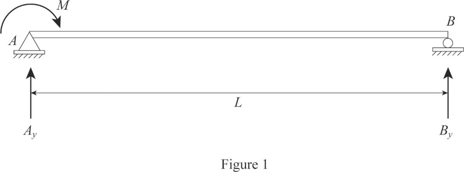
Refer Figure (1),
Find the reaction at support B.
Find the reaction at support A.
Draw the section at x distance from support A as in Figure (2).
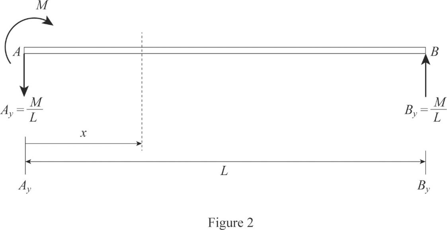
Refer Figure (2),
Write the equation for bending moment at x distance.
Write the equation for
Integrate Equation (1) to find the equation of the slope.
Integrate Equation (2) to find the equation of the deflection.
Find the integration constants
Apply boundary conditions in Equation (3):
At x=0 and y=0.
At x=L and y=0.
Find the equation of the slope.
Substitute
Thus, the equation of the slope is
Find the equation of the deflection.
Substitute
Thus, the equation of the deflection is
Want to see more full solutions like this?
Chapter 6 Solutions
Structural Analysis (MindTap Course List)


- Assume that in earthquake-resistant design, the following relations take place: Y=ce, where Y is the ground motion intensity at the building site, X is the magnitude of an earthquake, and the constant c is related to the distance between the site and center of the earthquake. Assuming that X is exponentially distributed, fx (x)=ex with x 20 and >2, (a) Derive the PDF and CDF of Y, including the bounds, and sketch them. (b) Determine the median (i.e., 50%-fractile) and 90%-fractile (value of Y that has a probability of not being exceeded of 90%) of Y. (c) Determine the mean and variance of Y by using the PDF of Y derived under (a). (d) Determine the mean and variance of Y directly from the PDF of X.arrow_forward== = Q1/A cantilever sheet-pile wall penetrating a granular soil. Here, Li= 3 m, L2 = 6 m, y 17.3kN/m³, Ysat 19.4 kN/m², and 0= 30. a. What is the theoretical depth of embedment, D? b. For a 30% increase in D, what should be the total length of the sheet piles? c. What should be the minimum section modulus of the sheet piles? Use σall = 172 MN/m².arrow_forwardFor the truss shown in Fig 2, determine the nodal displacement and member forces using the stifness method for all elements of the truss. Assume for each member A = 0.0015 m2 and E = 200 GPa please show all workingarrow_forward
- A tension member made of L4x4x1/2 is connected to gusset plate with welds. Using E70electrode and ½ inch weld size, design the balanced weld lengths.( Use AISC manual, LRFD units)(Previous solution was incorrect)arrow_forwardQ1: determine the area of steel for the slab that rests on brick walls and is shown in the figure. Use the following data: f'c = 25 MPa, fy = 420 MPa, L.L. = 1.5 kN/m², D.L. = 3 kN/m² (without self-weight). Rate from (1 to 4) your ability to solve the problem 7 m 0.3 m 0.3 marrow_forwardA rigging job calls for lifting a structure that weighs 150 tons. Two cranes are available, one with a rated capacity of 85 tons and the other with a rated capacity of 120 tons. The total weight of the rigging required to make the lift is 15 tons, of which 10 tons is to be carried by the larger craneand 5 tons is to be carried by the smaller crane. If the cranes are to be loaded in proportion to their net capacities, what should be the approximate net load on the 120-ton crane?arrow_forward
- I need detailed help solving this exercise from homework of Engineering Mathematics II.I do not really understand how to do, please do it step by step, not that long but clear. Thank you!P.S.: Please do not use AI, thanks!arrow_forwardI need detailed help solving this exercise from homework of Engineering Mathematics II.I do not really understand how to do, please do it step by step, not that long but clear. Thank you!P.S.: Please do not use AI, thanks!arrow_forwarda) For the truss shown in Fig 2, determine the stiffness matrices of elements 2, 3 and 4 in the in the global co-ordinate system. Assume for each member A = 0.0015 m2 and E = 200 GPa. Indicate the degrees-of freedom in all the stiffness matrices. b) Determine the stiffness matrix of the whole truss in the global co-ordinate system. Clearly indicate the degrees-of freedom numbers in the stiffness matrix. c) Calculate all the nodal displacements and all the member forces of the truss.arrow_forward
- I want an answer very quickly, pleasearrow_forwardI want an answer very quickly, pleasearrow_forwardQ1/ Choose the correct answer for the following: 1- Cantilever retaining walls is suitable for retaining backfill about a- 8m d-4m b- 12m c- 2m e- Any height 2-The shear key is provided to a- Avoid friction behind the wall d- All of the above b- Improve appearance e- None of the above c- Increase passive resistance types of retaining wall may b- Semi-gravity retaining walls d-Counterfort retaining walls be classified as follows: 3- The common a- Gravity retaining walls walls c- Cantilever retaining e- All the mentioned 4-Related to Stability of RW, Which of the following does not represent a potential failure mode for a retaining wall? a-Bearing capacity failure of the foundation soil. b- Wall cracking due to thermal expansion. c- Excessive settlement due to weak soil layer. d- Shear failure within the foundation soil adjacent to the wall. e-Sliding along the base due to insufficient friction. 5- If the desired factor of safety against sliding is not met, which strategy is NOT a…arrow_forward
