Videos
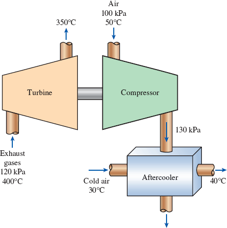
The turbocharger of an internal combustion engine consists of a turbine and a compressor. Hot exhaust gases flow through the turbine to produce work, and the work output from the turbine is used as the work input to the compressor. The pressure of ambient air is increased as it flows through the compressor before it enters the engine cylinders. Thus, the purpose of a turbocharger is to increase the pressure of air so that more air gets into the cylinder. Consequently, more fuel can be burned and more power can be produced by the engine.
In a turbocharger, exhaust gases enter the turbine at 400°C and 120 kPa at a rate of 0.02 kg/s and leave at 350°C. Air enters the compressor at 50°C and 100 kPa and leaves at 130 kPa at a rate of 0.018 kg/s. The compressor increases the air pressure with a side effect: It also increases the air temperature, which increases the possibility that a gasoline engine will experience an engine knock. To avoid this, an aftercooler is placed after the compressor to cool the warm air with cold ambient air before it enters the engine cylinders. It is estimated that the aftercooler must decrease the air temperature below 80°C if knock is to be avoided. The cold ambient air enters the aftercooler at 30°C and leaves at 40°C. Disregarding any frictional losses in the turbine and the compressor and treating the exhaust gases as air, determine (a) the temperature of the air at the compressor outlet and (b) the minimum volume flow rate of ambient air required to avoid knock.
FIGURE P5–188
(a)
The temperature of the air at the compressor outlet.
Answer to Problem 187RP
The temperature of the air at the compressor outlet is
Explanation of Solution
Draw the schematic diagram of the given turbo charger of the engine as shown in
Figure 1.
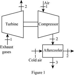
Write the general energy rate balance equation.
Here, the rate of heat transfer is
The system is at steady state. Hence, the rate of change in net energy of the system becomes zero.
Refer Figure 1 and Refer Equation (I).
For turbine:
Consider the turbine is adiabatic, neglect the heat transfer. Also neglect the kinetic and potential energy changes. The work done is by the system (turbine) and the work done on the system is zero i.e.
The Equations (I) reduced as follows to obtain the work output of compressor.
The change in enthalpy is expressed as follow.
Here, the specific heat of exhaust gas is
Substitute
For compressor:
Consider the compressor is adiabatic, neglect the heat transfer. Also neglect the kinetic and potential energy changes. The work done is on the system (compressor) and the work done by the system is zero i.e.
The Equations (I) reduced as follows to obtain the work input of compressor.
Here, the mass flow rate is
Refer Table A-2(b), “Ideal-gas specific heats of various common gases”.
The specific heat at constant pressure
The specific heat at constant pressure
The specific heat at constant pressure
Conclusion:
Substitute
Here,
Substitute
Thus, the temperature of the air at the compressor outlet is
(b)
The minimum volume flow rate of ambient air required to avoid knock.
Answer to Problem 187RP
The minimum volume flow rate of ambient air required to avoid knock is
Explanation of Solution
Refer Figure 1 and Refer Equation (I).
For aftercooler:
The after cooler is the two inlet and two outlet system.
Refer the Equation (I) Express the energy rate balance equation for aftercooler as follows
Here, subscript
Write the formula for volume flow rate of cold air.
Here, the gas constant of air is
Refer Table A-1, “Molar mass, gas constant, and critical-point properties”.
The gas constant
Conclusion:
Substitute,
Substitute
Thus, the minimum volume flow rate of ambient air required to avoid knock is
Want to see more full solutions like this?
Chapter 5 Solutions
Thermodynamics: An Engineering Approach


- 2. Figure below shows a U-tube manometer open at both ends and containing a column of liquid mercury of length l and specific weight y. Considering a small displacement x of the manometer meniscus from its equilibrium position (or datum), determine the equivalent spring constant associated with the restoring force. Datum Area, Aarrow_forward1. The consequences of a head-on collision of two automobiles can be studied by considering the impact of the automobile on a barrier, as shown in figure below. Construct a mathematical model (i.e., draw the diagram) by considering the masses of the automobile body, engine, transmission, and suspension and the elasticity of the bumpers, radiator, sheet metal body, driveline, and engine mounts.arrow_forward3.) 15.40 – Collar B moves up at constant velocity vB = 1.5 m/s. Rod AB has length = 1.2 m. The incline is at angle = 25°. Compute an expression for the angular velocity of rod AB, ė and the velocity of end A of the rod (✓✓) as a function of v₂,1,0,0. Then compute numerical answers for ȧ & y_ with 0 = 50°.arrow_forward
- 2.) 15.12 The assembly shown consists of the straight rod ABC which passes through and is welded to the grectangular plate DEFH. The assembly rotates about the axis AC with a constant angular velocity of 9 rad/s. Knowing that the motion when viewed from C is counterclockwise, determine the velocity and acceleration of corner F.arrow_forward500 Q3: The attachment shown in Fig.3 is made of 1040 HR. The static force is 30 kN. Specify the weldment (give the pattern, electrode number, type of weld, length of weld, and leg size). Fig. 3 All dimension in mm 30 kN 100 (10 Marks)arrow_forward(read image) (answer given)arrow_forward
- A cylinder and a disk are used as pulleys, as shown in the figure. Using the data given in the figure, if a body of mass m = 3 kg is released from rest after falling a height h 1.5 m, find: a) The velocity of the body. b) The angular velocity of the disk. c) The number of revolutions the cylinder has made. T₁ F Rd = 0.2 m md = 2 kg T T₂1 Rc = 0.4 m mc = 5 kg ☐ m = 3 kgarrow_forward(read image) (answer given)arrow_forward11-5. Compute all the dimensional changes for the steel bar when subjected to the loads shown. The proportional limit of the steel is 230 MPa. 265 kN 100 mm 600 kN 25 mm thickness X Z 600 kN 450 mm E=207×103 MPa; μ= 0.25 265 kNarrow_forward
- T₁ F Rd = 0.2 m md = 2 kg T₂ Tz1 Rc = 0.4 m mc = 5 kg m = 3 kgarrow_forward2. Find a basis of solutions by the Frobenius method. Try to identify the series as expansions of known functions. (x + 2)²y" + (x + 2)y' - y = 0 ; Hint: Let: z = x+2arrow_forward1. Find a power series solution in powers of x. y" - y' + x²y = 0arrow_forward
 Elements Of ElectromagneticsMechanical EngineeringISBN:9780190698614Author:Sadiku, Matthew N. O.Publisher:Oxford University Press
 Mechanics of Materials (10th Edition)Mechanical EngineeringISBN:9780134319650Author:Russell C. HibbelerPublisher:PEARSON
 Thermodynamics: An Engineering ApproachMechanical EngineeringISBN:9781259822674Author:Yunus A. Cengel Dr., Michael A. BolesPublisher:McGraw-Hill Education
 Control Systems EngineeringMechanical EngineeringISBN:9781118170519Author:Norman S. NisePublisher:WILEY
 Mechanics of Materials (MindTap Course List)Mechanical EngineeringISBN:9781337093347Author:Barry J. Goodno, James M. GerePublisher:Cengage Learning
 Engineering Mechanics: StaticsMechanical EngineeringISBN:9781118807330Author:James L. Meriam, L. G. Kraige, J. N. BoltonPublisher:WILEY