
Beams AB, BC, and CD have the cross section shown and are pin-connected at B and C. Knowing that the allowable normal stress is +110 MPa in tension and –150 MPa in compression, determine (a) the largest permissible value of P if beam BC is not to be overstressed, (b) the corresponding maximum distance a for which the cantilever beams AB and CD are not overstressed.
Fig. P5.90
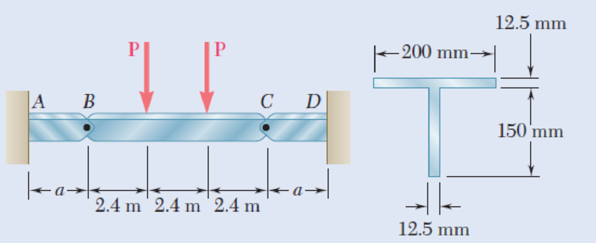
(a)
The largest permissible value of P for the condition that the beam BC is not overstressed.
Answer to Problem 90P
The largest permissible value of P is
Explanation of Solution
Given information:
The allowable normal stress of the material in tension is
The allowable normal stress of the material in compression is
Calculation:
Show the free-body diagram of the section BC as in Figure 1.
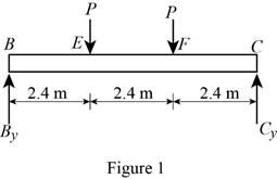
Determine the vertical reaction at point C by taking moment about point B.
Determine the vertical reaction at point B by resolving the vertical component of forces.
Show the free-body diagram of the section AB as in Figure 2.
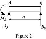
Determine the vertical reaction at point A by resolving the vertical component of forces.
Determine the moment at point A by taking moment about the point A.
Show the free-body diagram of the section CD as in Figure 3.
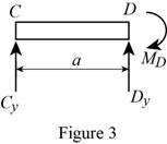
Determine the vertical reaction at point D by resolving the vertical component of forces.
Determine the moment at point D by taking moment about the point D.
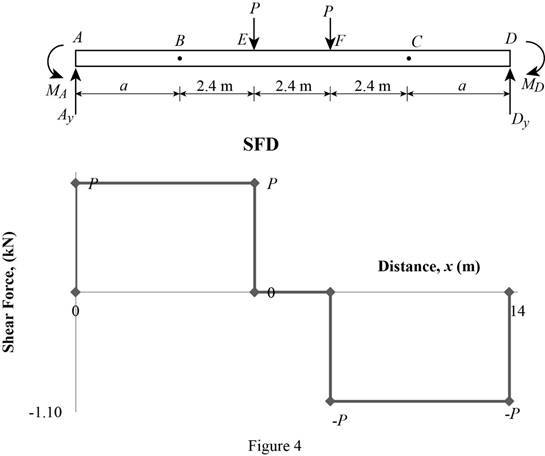
Shear force:
Show the calculation of shear force as follows;
Show the calculated shear force values as in Table 1.
| Location (x) m | Shear force (V) kN |
| A | P |
| E (Left) | P |
| E (Right) | 0 |
| F (Left) | 0 |
| F (Right) | –P |
| D | –P |
Plot the shear force diagram as in Figure 4.
Bending moment:
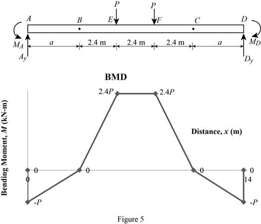
Show the calculation of the bending moment as follows;
Show the calculated bending moment values as in Table 2.
| Location (x) m | Bending moment (M) kN-m |
| A | Pa |
| B | 0 |
| E | 2.4P |
| F | 2.4P |
| C | 0 |
| D | –Pa |
Plot the bending moment diagram as in Figure 5.
Show the free-body diagram of the T-section as in Figure 6.
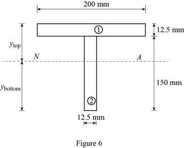
Determine the centroid in y-axis
Here, the area of the section 1 is
Refer to Figure 4;
Substitute
Determine the moment of inertia (I) using the equation.
Here, the depth of the section 1 is
Substitute 12.5 mm for
Refer to Figure 4;
Tension at Points B and D:
Refer to Figure 5;
Determine the moment at points B and D using the relation.
Substitute 110 MPa for
Compression at Points B and C:
Refer to Figure 5;
Determine the moment at points B and D using the relation.
Substitute –150 MPa for
Tension at maximum bending moment:
Refer to Figure 5;
Determine the maximum moment using the relation.
Substitute 110 MPa for
Compression at maximum bending moment:
Refer to Figure 5;
Determine the maximum moment using the relation.
Substitute –150 MPa for
Refer to the calculated distribution loads; the smallest value controls the design.
Refer to Figure 5;
Equate the maximum bending moment calculated and the maximum bending moment in the tension side.
Therefore, the largest permissible value of P for the condition that the beam BC is not overstressed is
(b)
The maximum distance a for the condition that the beams AB and CD are not overstressed.
Answer to Problem 90P
The maximum distance a for the condition that the beams AB and CD are not overstressed is
Explanation of Solution
Refer to Part (a), Figure 4;
The maximum bending moment in the beams AB and CD occurs at the ends A and D.
The calculated maximum bending moment at the points A and D is as follows:
The maximum allowable compression moment at the points A and D is as follows:
Equate the values;
Refer to the answer of the part (a);
Substitute 4.01 kN for P.
Therefore, the maximum distance a for the condition that the beams AB and CD are not overstressed is
Want to see more full solutions like this?
Chapter 5 Solutions
Mechanics of Materials, 7th Edition
- ۳/۱ العنوان O не شكا +91x PU + 96852 A heavy car plunges into a lake during an accident and lands at the bottom of the lake on its wheels as shown in figure. The door is 1.2 m high and I m wide, and the top edge of Deine the hadrostatic force on the Plot the displacement diagram for a cam with roller follower of diameter 10 mm. The required motion is as follows; 1- Rising 60 mm in 135° with uniform acceleration and retardation motion. 2- Dwell 90° 3- Falling 60 mm for 135° with Uniform acceleration-retardation motion. Then design the cam profile to give the above displacement diagram if the minimum circle diameter of the cam is 50 mm. = -20125 750 x2.01arrow_forwardPlot the displacement diagram for a cam with roller follower of diameter 10 mm. The required motion is as follows; 1- Rising 60 mm in 135° with uniform acceleration and retardation motion. 2- Dwell 90° 3- Falling 60 mm for 135° with Uniform acceleration-retardation motion. Then design the cam profile to give the above displacement diagram if the minimum circle diameter of the cam is 50 mm.arrow_forwardQ1/ A vertical, circular gate with water on one side as shown. Determine the total resultant force acting on the gate and the location of the center of pressure, use water specific weight 9.81 kN/m³ 1 m 4 marrow_forward
- I need handwritten solution with sketches for eacharrow_forwardGiven answers to be: i) 14.65 kN; 6.16 kN; 8.46 kN ii) 8.63 kN; 9.88 kN iii) Bearing 6315 for B1 & B2, or Bearing 6215 for B1arrow_forward(b) A steel 'hot rolled structural hollow section' column of length 5.75 m, has the cross-section shown in Figure Q.5(b) and supports a load of 750 kN. During service, it is subjected to axial compression loading where one end of the column is effectively restrained in position and direction (fixed) and the other is effectively held in position but not in direction (pinned). i) Given that the steel has a design strength of 275 MN/m², determine the load factor for the structural member based upon the BS5950 design approach using Datasheet Q.5(b). [11] ii) Determine the axial load that can be supported by the column using the Rankine-Gordon formula, given that the yield strength of the material is 280 MN/m² and the constant *a* is 1/30000. [6] 300 600 2-300 mm wide x 5 mm thick plates. Figure Q.5(b) L=5.75m Pinned Fixedarrow_forward
- Q1: For the following force system, find the moments with respect to axes x, y, and zarrow_forwardQ10) Body A weighs 600 lb contact with smooth surfaces at D and E. Determine the tension in the cord and the forces acting on C on member BD, also calculate the reaction at B and F. Cable 6' 3' wwwarrow_forwardHelp ارجو مساعدتي في حل هذا السؤالarrow_forward
 Elements Of ElectromagneticsMechanical EngineeringISBN:9780190698614Author:Sadiku, Matthew N. O.Publisher:Oxford University Press
 Mechanics of Materials (10th Edition)Mechanical EngineeringISBN:9780134319650Author:Russell C. HibbelerPublisher:PEARSON
 Thermodynamics: An Engineering ApproachMechanical EngineeringISBN:9781259822674Author:Yunus A. Cengel Dr., Michael A. BolesPublisher:McGraw-Hill Education
 Control Systems EngineeringMechanical EngineeringISBN:9781118170519Author:Norman S. NisePublisher:WILEY
 Mechanics of Materials (MindTap Course List)Mechanical EngineeringISBN:9781337093347Author:Barry J. Goodno, James M. GerePublisher:Cengage Learning
 Engineering Mechanics: StaticsMechanical EngineeringISBN:9781118807330Author:James L. Meriam, L. G. Kraige, J. N. BoltonPublisher:WILEY


